Download

1 / 44
440 likes | 599 Views
Microscopy and Surface Analysis 2. Lecture Date: March 25 th , 2013. Basic Considerations for Surface Spectroscopy. Common sampling “modes” Spot sampling Raster scanning Depth profiling Surface contamination:

E N D
Microscopy and Surface Analysis 2 Lecture Date: March 25th, 2013
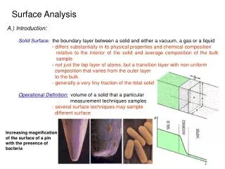
Basic Considerations for Surface Spectroscopy • Common sampling “modes” • Spot sampling • Raster scanning • Depth profiling • Surface contamination: • The obvious contamination/alteration of surfaces that can be the result of less-than careful sample preparation • Solid surfaces can adsorb gases: • At 10-6 torr, a complete monolayer of a gas (e.g. CO) takes just 3 seconds to form. • At 10-8 torr, monolayer formation takes 1 hour. • Most studies are conducted under vaccuum – although there are newer methods that don’t require this. D. M. Hercules and S. H. Hercules, J. Chem. Educ., 1984, 61, 403.
Surface Spectrometric Analysis • Surface spectrometric techniques: • X-ray fluorescence (from electron microscopy) • Auger electron spectrometry • X-ray photoelectron spectrometry (XPS/UPS) • Secondary-ion mass spectrometry (SIMS) • Depth profiling – if you are going to study surfaces with high lateral resolution (e.g. using microscopy), then wouldn’t it be nice to obtain information from various depths within the sample?
The Basic Idea Behind Surface Spectrometry Primary photon electron ion Secondary photon electron ion Photons, electrons, ions: they can go in and/or out!!! Leads to lots of techniques, and lots of acronyms! Surface
Electron Microprobes and X-ray Emission • Electron microscopy (usually SEM) can also be used to perform X-ray emission analysis in a manner similar to X-ray fluorescence analysis • see the X-ray spectrometry lecture for details on the spectra • The electron microprobe (EM) is the commonly used name for this type of X-ray spectrometry • Both WDS and EDS detectors are used (as in XRF), elemental mapping • This technique is not particularly surface sensitive!
Electron Spectroscopy • Spectroscopic methods that measure electron energies (electron spectroscopy) are often surface sensitive, because electrons can’t escape from deep inside a material • Major forms of electron spectroscopy: • Auger electron spectroscopy • X-ray/UV photoelectron spectroscopy • Electron energy loss spectroscopy (EELS)
Electron Spectroscopy: Surface Sensitivity • Electrons can only escape from shallow depths in the surface of a sample, because they will undergo collisions and lose energy. XPS/AES region, electrons that have not been inelastically scattered from shallow regions (mostly excitation of conduction-band electrons) Deep electrons that undergo inelastic collisions but lose energy (exciting e.g. phonons)
Auger Electron Spectrometry (AES) • The Auger process can also be a source of spectral information. Auger electrons are expelled from atomic/molecular orbitals and their kinetic energy is characteristic of atoms/molecules • However, since it is an electron process, analysis of electron energy is necessary! • This is unlike the other techniques we have discussed, most of which measure photon wavelengths or energy • Auger electron emission is a three-step (three electron) process, that leaves an atom doubly-ionized
AES: Basic Mechanism See Figure 21-7 in Skoog, et al. for a related figure.
AES: Naming Auger Electrons • Auger electrons are created from outer energy levels (i.e. less-tightly bound electrons, possibly valence levels). • Their name indicates their origin: This example would be called a LMM Auger electron. Other Common types are denoted KLL and MNN.
AES: Efficiency of Auger Electron Production • Two competing processes: • X-ray fluorescence • Auger electron emission • Auger electrons predominate at lower atomic number (Z) • Photoelectron emission does not compete! Top Figure from Strobel and Heineman, Chemical Instrumentation, A Systematic Approach, Wiley, 1989.
AES: Spectrometer Design • AES instruments are designed like an SEM – often they are integrated with an SEM/EDXA system • Unlike an SEM, AES instruments are designed to reach higher vacuum (10-8 torr) • Helps keep surfaces clean and free from adsorbed gases, etc… • Basic components: • Electron source/gun • Electron energy analyzer • Electron detector • Control system/computer • Ion gun (for depth profiling) Electron Gun Electron detector Energy analyzer Ion Gun Auger electrons Sample
AES (and XPS): Electron Energy Analyzers • Two types of electron energy analyzers (also used in XPS): Electrons only pass if their KE is: Concentric hemispherical analyzer (higher resolution) – better resolution, mostly for XPS/UPS Cylindrical mirror analyzer (higher efficiency) More common for AES (Right) Diagram from http://www.cea.com/cai/auginst/caiainst.htm (Left) Diagram from Strobel and Heineman, Chemical Instrumentation, A Systematic Approach, Wiley, 1989.
AES: Detectors • More sophisticated detectors are needed to detect low numbers of Auger electrons. Two types of electron-multiplier detectors (adapted from MS detectors): Discrete dynode Continuous dynode • Both types of detector are also used in XPS/UPS!!!
AES: Surface Analysis • AES is very surface sensitive (10-50 Ǻ) and its reliance on an electron beam results in excellent lateral resolution • The electron beam does not have to be monochromatic • Note: an X-ray beam can also be used for AES, but is less desirable b/c it cannot currently be focused as tightly (as is the case in XPS) • Auger electrons typically have energies of < 1000 eV, so they are only emitted from surface layers. Diagram from http://www.cea.com/cai/auginst/caiainst.htm
AES: Spectral Interpretation • AES Electron Kinetic Energies* versus Atomic Number • (Most intense peaks only. Valid for CMA-type analyzers.) *Data is from J.C. Vickerman (Ed.), "Surface Analysis: The Principal Techniques“, John Wiley and Sons, Chichester, UK, 1997 . Image from http://www.cem.msu.edu/~cem924sg/KineticEnergyGraph.html (accessed 12-Nov-2004)
AES: Elemental Surface Analysis • Very common application of AES - elemental surface analysis • For true surface analysis, AES is better than SEM/X-ray emission (electron microprobe) because it is much more surface sensitive • AES can be easily made quantitative using standards. Image from http://www.cem.msu.edu/~cem924sg/ (accessed 12-Nov-2004)
AES: Chemical Shifts • Chemical information (i.e. on bonding, oxidation states) should be found in Auger spectra because the electron energy levels are sensitive to the chemical environment. • In practice, it is usually not found because too many electron energy levels are involved – it is difficult to calculate and simulate Auger spectra.
X-ray Photoelectron Spectrometry (XPS) • Photoelectron spectroscopy is used for solids, liquids and gases, but has achieved prominence as an analytical technique for solid surfaces • XPS: “soft” x-ray photon energies of 200-2000 eV for analysis of core levels • UPS: vacuum UV energies of 10-45 eV for analysis of valence and bonding electrons • Photoelectric effect: Proposed by A. Einstein (1905), harnessed by K. Siegbahn (1950-1970) to develop XPS
XPS: Basic Concepts • Like Auger electrons, photoelectrons can not escape from depths greater than 10-50 A inside a material • Schematically, the photoelectron process is: atom or molecule cation • Like in AES, the kinetic energy of the emitted electron is measured in a spectrometer
XPS: Photoelectron Emission and Binding Energy • The kinetic energy of the emitted electron can be related to the “binding energy”, or the energy required to remove an electron from its orbital. • Higher binding energies mean tighter binding – e.g. as atomic number goes up, binding energies get tighter because of increasing number of protons. (gas) (solid) http://www.chem.qmw.ac.uk/surfaces/scc/scat5_3.htm
Quick Review of Electron Energy levels in Solids • In solids, atomic and molecular energy levels broaden into bands that in principle contain as many states as there are atoms/molecules in the solid. • Bands may be separated by a band gap with energy Eg P.A. Cox, "The Electronic Structure and Chemistry of Solids" Oxford University Press, 1987. C. Kittel, Solid-state Physics, 7th Ed, Wiley, 1999. W. A. Harrison, Electronic Structure and the Properties of Solids, Dover, 1989.
Energy Bands in the Solid State • Bands are continuous and delocalized over the material • Band “widths” are determined by size of orbital overlap • The highest-energy filled band (which may be only partially filled) is called the valence band • The lowest-energy empty band is called the conduction band P.A. Cox, "The Electronic Structure and Chemistry of Solids" Oxford University Press, 1987. C. Kittel, Solid-state Physics, 7th Ed, Wiley, 1999. W. A. Harrison, Electronic Structure and the Properties of Solids, Dover, 1989.
The Workfunction: A Barrier to Electron Emission • How does the electronic arrangement in solids affect surfaces? In particular, how can an electron be removed? Free electron! • For some electron being removed, its energy just as it gets free is EV • The energy required to remove the electron is the workfunction (typically several eV) P.A. Cox, "The Electronic Structure and Chemistry of Solids" Oxford University Press, 1987. C. Kittel, Solid-state Physics, 7th Ed, Wiley, 1999. W. A. Harrison, Electronic Structure and the Properties of Solids, Dover, 1989.
The Workfunction: A Barrier to Electron Emission • Workfunctions vary from <2 eV for alkali metals to >5 eV for transition metals. • The workfunction is the ‘barrier” to electron emission – like the wall in the particle-in-a-box concept. Data from CEM 924 Lectures presented at MSU (2001).
XPS: Binding Energy • The workfunction w is usually linked to the spectrometer (if the sample is electrically connected) • In gases, the BE is directly related to IP • Ionization potential – the energy required to take an electron out of its orbital all the way to the “vacuum” (i.e. far away!) • PE spectroscopy on gases is used to check the accuracy of modern quantum chemical calculations • In conducting solids the workfunction is involved • Koopman’s Theorem: binding energy = -(orbital energy) • Orbital energies can be calculated from Hartree-Fock • Another definition for XPS binding energy: the minimum energy required to move an inner electron from its orbital to a region away from the nuclear charge. Absorption edges result from this same effect
XPS: Sources • Monochromatic sources using electrons fired at elemental targets that emit x-rays. • Can be coupled with separate post-source monochromators containing crystals, for high resolution (x-ray bandwidth of <0.3 Å) • XPS Sources (hit core electrons): • Mg Ka radiation: hn = 1253.6 eV • Al Ka radiation: hn = 1486 eV • AgLa radiation: hn = 2984.3 eV • UPS Sources (hit valence electrons): • He(I) radiation:hn = 21.2 eV (~58.4 nm) • hn = 23 eV (~53.7 nm) • He(II) radiation: hn = 41 eV (~30.4 nm) • Focusing the spot and lateral resolution - 10-m diameter spots are now possible A Thermo-Electron Dual-anode (Al/Mg) XPS source
XPS: Spectral Interpretation • Orbital binding energies can be interpreted based on correlation tables, empirical trends and theoretical analysis. • Peaks appear in XPS spectra for distinguishable atomic and molecular orbitals. • Auger peaks also appear in XPS spectra – they are easily distinguished by comparing the XPS spectra from two sources (e.g. Mg and Al K lines). The Auger peaks remain unchanged with respect to kinetic energy, while the XPS peaks shift.
XPS: Binding Energy Ranges • XPS Photoelectron Binding Energies versus Atomic Number (Z) *Data from C.D. Wagner, W.M. Riggs, L.E. Davis, J.F. Moulder and G.E. Muilenberg, Eds., "Handbook of X-ray Photoelectron Spectroscopy," Perkin-Elmer Corp., Flying Cloud, MN, 1979. Image from http://www.cem.msu.edu/~cem924sg/BindingEnergyGraph.html (accessed 12-Nov-2004)
XPS: Typical Spectra • An XPS survey spectrum of stainless steel: Spectrum image from http://www.mee-inc.com/esca.html
XPS: Typical Spectra • An expanded XPS spectrum of the C1s region of PET: Spectrum image from http://www.mee-inc.com/esca.html
XPS: Chemical Shifts • Peaks appear in XPS spectra for distinguishable atomic and molecular orbitals. • Effects that cause chemical shifts in XPS spectra: • Oxidation states • Covalent structure • Neighboring electron withdrawing groups • Anything else that can affect ionization/orbital energies
XPS: Depth Profiling • Option 1: Sputtering techniques • Disadvantage – can damage the surface • Advantage – wide range of depths can be sampled (just keep sputtering), e.g. 100 A • Option 2: Angle-resolved XPS (AR-XPS) • Reducing the photoelectron take-off angle (measured from the sample surface) reduces the depth from which the XPS information is obtained. XPS is more surface sensitive for grazing take-off angles than for angles close to the surface normal (longer PE paths). • The most important application of angle resolved XPS (AR-XPS) is in the estimation of the thickness of thin films e.g. contamination, implantation, sputtering-altered and segregation layers. normal electron grazing Sample For more on AR-XPS, see Briggs and Seah, Practical Surface Analysis, 2nd Ed., Vol. 1. “Auger and X-ray Photoelectron Spectroscopy,” Wiley, 1990, pp. 183-186, 244-250
Depth Profiling with Angle-Resolved XPS • AR-XPS data is often acquired by tilting the specimen • Example: gallium arsenside with a thin oxide layer on its surface: bulk electron Grazing angle (X-ray takeoff angle) surface (grazing) Sample AR-XPS figure from C. R. Brundle, J. F. Watts and J. Wolstenholme, in Ewing’s Analytical Instrumentation Handbook 3rd Ed., Dekker 2005.
XPS: Applications • A modern application of XPS – study the nature of PEG as a surface coating to prevent biofouling in biosensors • Biofouling: the tendency of proteins to adsorb to silicon-based surfaces • XPS can be used, with AFM, to observe the coating of PEG onto silicon surfaces (PEG-silane coupling) - Increased C 1s C-O signal indicates greater grafting density S. Sharma, et al., “XPS and AFM analysis of antifouling PEG interfaces for microfabricated silicon biosensors”, Biosensors and Bioelectronics, 20 227–239 (2004).
XPS: Quantitative Applications • Quantitative XPS is not as widely used as the qualitative version of the technique. • Variations in instrument parameters and set-up have traditionally caused problems with reproducibility • Using internal standards, XPS can achieve quantitative accuracies of 3-10% in most cases (and getting better every year, as more effort is put into this type of analysis)
AES and XPS: Combined Systems • Dual Auger/XPS systems are very common, also combined with a basic SEM • Note - SAM = scanning Auger microprobe • Auger is seen as complementary to XPS with generally better lateral resolution • Both are extreme surface sensitive techniques: • AES better elemental quantitative analysis • XPS contains more chemical information • Also, remember that Auger peaks are often seen in XPS spectra (and are hence useful analytically) – they can be identified by changing source, so that the X-ray peaks shift (the Auger peaks do not).
Comparison of XPS, AES and Other Techniques * = yes, with compensation for the effects of sample charging SIMS = secondary ion mass spectrometry, discussed in the “Ion and Particle Spectrometry” Lectures. See Strobel and Heineman, Chemical Instrumentation, A Systematic Approach, Wiley, 1989, pg. 832.
XPS: New Applications • A recent report in Chem. Commun. (2005) by Peter Licence and co-workers describes the use of XPS to study ionic liquids • Normal liquids evaporate under ultrahigh vacuum (UHV), ionic liquids do not (they have a vapor pressure of nearly zero!) • Why? Ionic liquids have become important for electrochemistry, catalysis, etc… • See C&E News Oct. 31, 2005, pg 10.
Further Reading Hand-out Review Article: C. R. Brundle, J. F. Watts, and J. Wolstenholme, “X-ray Photoelectron and Auger Electron Spectroscopy”, in Ewing’s Analytical Instrumentation Handbook, 3rd Ed. (J. Cazes, Ed.), Marcel-Dekker 2005. Electron Microscopy and Electron Microprobe/X-ray Emission Analysis 1. J. I. Goldstein et al., Scanning Electron Microscopy and X-ray Microanalysis, 3rd Ed., Kluwer Academic, 2003. 2. J. J. Bozzola et al., Electron Microscopy: Principles and Techniques for Biologists, 2nd Ed., Jones and Bartlett, 1998. 3. J. W. Edington, N. V Philips, Practical Electron Microscopy in Materials Science, Eindhoven, 1976. Electron Microscopy and Electron Diffraction/Electron Energy Loss Spectroscopy 4. A. Engel and C. Colliex, “Application of scanning transmission electron microscopy to the study of biological structure”, Current Biology4, 403-411 (1993). (STEM and EELS) 5. W. Chiu and M. F. Schmid, “Electron crystallography of macromolecules”, Current Biology4, 397-402 (1993). (ED and LEED) 6. W. Chiu, “What does electron cryomicroscopy provide that X-ray crystallography and NMR cannot?”, Annu. Rev. Biophys. Biomol. Struct., 22, 233-255 (1993). (Electron Cryomicroscopy/Imaging) 7. L. Tang and J. E. Johnson, “Structural biology of viruses by the combination of electron cryomicroscopy and X-ray crystallography”, 41, 11517-11524 (2002). (Electron Cryomicroscopy/Imaging) Optical Microscopy 8. R. H. Webb, "Confocal optical microscopy“, Rep. Prog. Phys.59, 427-471 (1996). Force Microscopy: 9. R. J. Hamers, “Scanned probe microscopies in chemistry,” J. Phys. Chem., 100, 13103-13120 (1996).
Further Reading Surface Spectrometric Methods (XPS and AES) 10. T. L. Barr, Modern XPS, Boca Raton: CRC Press (1994). 11. M. Thompson, M. D. Baker, A. Christie, and J. F. Tyson, Auger Electron Spectroscopy, New York: Wiley (1985). 12. N. H. Turner, “X-ray Photoelectron and Auger Electron Spectroscopy”, Applied Spectroscopy Reviews, 35 (3), 203-254 (2000).