SIDE CAM
SIDE CAM. NAMES 1-RAMY EBRAHEM ABDEL RAHMAN 2-MAHMOUD AHMED ABDEL RAOUF 3-MOHAMED MAGD ALDEEN MOHAMED 4-MAHMOUD LOTFY ELHADY 5-ADEL REFAT ABD ELQADER 6-AHMED MOHAMED ESAM SUPERVISED BY/ PROF.DR./SAAD ABDELHAMEED. Single Overhead Cam (OHC)/(SOHC).


SIDE CAM
E N D
Presentation Transcript
SIDE CAM • NAMES • 1-RAMY EBRAHEM ABDEL RAHMAN • 2-MAHMOUD AHMED ABDEL RAOUF • 3-MOHAMED MAGD ALDEEN MOHAMED • 4-MAHMOUD LOTFY ELHADY • 5-ADEL REFAT ABD ELQADER • 6-AHMED MOHAMED ESAM SUPERVISED BY/ PROF.DR./SAAD ABDELHAMEED
Single Overhead Cam (OHC)/(SOHC) • Single cam mounted in head. • Opens both intake and exhaust valves. • One cam on an inline engine and two cams on a vee engine.
Dual Overhead Cam (DOHC) • Camshafts mounted in cylinder head. • One cam opens intake valves and one opens exhaust valves. • Often used with 4 valves per cylinder. • Most high performance of all types. • Vee engines have 4 cams.
Overhead Valve Engines • Has valves in cylinder head increasing compression. • Camshaft still in block. • Uses lifters, pushrods and rocker arms. • Most common head design until 1990’s.
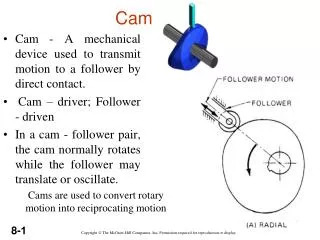
Camshafts • Opens the valves at the right time. • Actually converts rotary motion to reciprocating motion. • Uses a cam lobe for each valve. • Usually made of cast iron. • Has a great effect on engine performance. • Can be given auxiliary functions like running the oil pump or distributor.
CAMSHAFT CONSTRUCTION • Cam lobes • Camshaft thrust plate • Cam bearings • Cam housing and cam cover
Cam Lobe Terminology • Heel as known as the base circle. • Nose is the tip of the lobe which determines cam lift. • Opening and closing flanks and ramps. • Timing points are where the cam starts to open and close the valve.
Cam Lobe Lift • The distance the valve is pushed open. • It is determined by the height of the lobe.
Cam Duration • This chart is in degrees of crankshaft rotation. • Note when the valves open and close and on which strokes. This is the duration. • It’s not what it may seem to be!
Camshaft Drives • Gear on gear • Gear and chain • Belt and notched pulley • Cam gear ALWAYS is twice as large as the crank gear, this makes the cam turn at ½ the speed of the crank.
Gear to Gear Drive • Simplest drive system. • Reliable and strong but noisy. • Reverses Direction of Power 2 times CW>CCW>CW
Gear and Chain Drive • Quieter the gear types. • Allows cam to be further away from crankshaft.
Timing Belt • Used primarily on overhead cam engines. • Uses a kevlar belt. • (police vests) • Can snap or stretch causing catastrophic damage to non-free running engines. • Chains remain more popular with engine makers.
Pushrods • Metal rod which transfers force from the lifter to the rocker arm.
Push Rod The push rod is used to control the opening and closing of the valve. The push rod is controlled by the cam shaft. As the rod is pushed up by the lob on the cam shaft, the push rod forces the rocker arm to open the valve into the combustion chamber. The push rod is used in engines where the camshaft is located in the block of the engine.
VALVE LIFTERS • Solid Lifters • Roller Lifters • Hydraulic Lifters • Followers
Valve Lifter or Tappet • May be solid, roller, or hydraulic • The lifter follows the cam lobes and pushes on the pushrod • Solid and roller lifters require adjustable rocker arms • Hydraulic type lifters fill with oil and lengthen to compensate for any clearances in the valve system
Rocker Arms • Rocker arms are made of stamped steel, cast iron or aluminum. • They transmit the force of the pushrod to the valve. • Some have adjusters.
Reciprocating Engine Design and Construction • Rocker Arms • Transmits the lifting force from the cam to the valve.
Rocker Arms Roller- Stamped Adjuster Cast Pivot Stamped
Rocker arms • Wear on faces & push rod sockets • Wear in adjusting screws • Stamped rockers cannot be refaced • Forged, cast, & fabricated rockers can be refaced
Reciprocating Engine Design and Construction • Valves • Fuel/air mixture enters the cylinders through the intake valve. • Burned gases are expelled through the exhaust valve. • Mushroom or tulip type depending on shape.
Reciprocating Engine Design and Construction • Valve Construction • Intake valves, because of lower operating temperatures, can be made of chrome-nickel steel. • Exhaust valves are made of exotic metals such as inconel, silicon-chromium or cobalt-chromium alloys.
Tip Neck Face Head Reciprocating Engine Design and Construction • Valve Construction Stem
Reciprocating Engine Design and Construction • Valve Construction • Valve head has ground face which forms a seal against the ground valve seat in the cylinder head. • Valve face ground to an angle of either 30° or 45°. • Valve face made more durable by the application of stellite (an alloy of cobalt and chromium).
Reciprocating Engine Design and Construction • Valve Construction • Valve stem acts as a pilot for the valve head and rides in the valve guide. • Surface-hardened to resist wear. • Some stems are hollow and partially filled with metallic sodium.
Reciprocating Engine Design and Construction • Valve Construction • The neck is the part that forms the junction between the head and the stem. • The tip is hardened to with stand the hammering of the valve rocker arm.
Reciprocating Engine Design and Construction • Valve Construction • Machined groove near tip receives the split-ring keys which form a lock ring to hold the valve spring retaining washer.
Reciprocating Engine Design and Construction • Valve-Operating Mechanism • Each valve must open at the proper time, stay open for the required length of time, and close at the proper time. • Timing of the valves is controlled by the valve-operating mechanism.
Reciprocating Engine Design and Construction • Valve-Operating Mechanism • Intake valves open just before the piston reaches top dead center, and exhaust valves remain open after top dead center. • At this particular instant both valves are open at the same time (end of the exhaust stroke and beginning of the intake stroke). • This valve overlap results in better volumetric efficiency and lower operating temperatures.
Reciprocating Engine Design and Construction • Valve-Operating Mechanism (Opposed engine)
Reciprocating Engine Design and Construction • Valve-Operating Mechanism (Radial engine)
Reciprocating Engine Design and Construction • Valve Springs • Function is to close the valve and to hold the valve securely on the valve seat.
Reciprocating Engine Design and Construction • Valve Springs • Two or more springs used to eliminate spring vibration or surging during different engine speeds. • Held in place by split locks installed in the recess of the valve spring upper retainer washer.
Reciprocating Engine Design and Construction • Bearings
Reciprocating Engine Design and Construction • Bearings • Any surface which supports, or is supported by, another surface. • Composed of material that is strong enough to withstand the pressure imposed on it. • Permit the other surface to move with a minimum of friction and wear. • Lubricated bearings.
Reciprocating Engine Design and Construction • Bearings • Three types of lubricated bearings used: • Plain Bearings • Ball Bearings • Roller Bearings • Bearings are required to take radial loads, thrust loads, and a combination of the two.
Reciprocating Engine Design and Construction • Plain Bearings • Used for crankshaft, cam ring, camshaft, connecting rods, and accessory drive shaft. • Subjected to radial loads. • Made of nonferrous metals.
Reciprocating Engine Design and Construction • Ball Bearings • Used in supercharger impeller shaft bearings and rocker arm bearings. • Special deep groove ball bearings are used in some aircraft engines to transmit propeller thrust to the engines nose section.
Reciprocating Engine Design and Construction • Roller Bearings • Straight roller bearings used where the bearing is subjected to radial loads only. • Tapered roller bearings used where bearing is subjected to both radial and thrust loads.