Cam
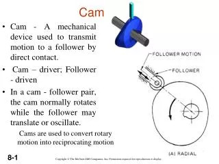
Cam. Cam - A mechanical device used to transmit motion to a follower by direct contact. Cam – driver; Follower - driven In a cam - follower pair, the cam normally rotates while the follower may translate or oscillate. Cams are used to convert rotary motion into reciprocating motion.

Cam
E N D
Presentation Transcript
Cam • Cam - A mechanical device used to transmit motion to a follower by direct contact. • Cam – driver; Follower - driven • In a cam - follower pair, the cam normally rotates while the follower may translate or oscillate. Cams are used to convert rotary motion into reciprocating motion
CAMS Follower motions having almost any desired characteristics are not difficult to design. By desired characteristics are typically meant the following: Displacement– the height or distance through which the follower is moved for one revolution of the cam; Velocity– the speed with which the cam moves the follower; Acceleration– the rate of change of velocity of the follower Jerk– the rate of change of acceleration.
CLASSIFICATION OF CAMS (i) Based on the physical shape (a) Disk or plate cams
Translation Cam (Wedge Cam) Not very commonly used. The cam moves over and back, reciprocating motion, which drives the follower vertically.
CLASSIFICATION OF FOLLOWES Based on surface in contact (a) Knife edge follower (b) Roller follower (c) Flat faced follower (d) Spherical follower
KNIFE OR POINT EDGE FOLLOWER FLAT FACED FOLLOWER ROLLER FOLLOWER
(ii) Based on type of motion • Oscillating follower • Translating follower
(iii) Based on line of action • Radial (in line) follower
1.2 Classification of CAM Mechanism Based on modes of Input / Output motion 1 Rotating cam –Translating follower 2 Rotating cam – Oscillating follower 3 Translating cam – Translating follower
Classification of followers According to the shape of follower • Knife edge follower • Roller follower • Flat faced follower • Spherical faced follower
Classification of cams • Radial or disc cam In radial cams, the follower reciprocates or oscillates in a direction perpendicular to the cam axis b) Cylindrical cam In cylindrical cams, the follower reciprocates or oscillates in a direction parallel to the cams axis. c) End cam It is also similar to cylindrical cams, but the follower makes contact at periphery of the cam.
Cam profile :The outer surface of the disc cam. • Base circle: The smallest circle drawn on the cam profile. • Trace point: The center line of the follower roller or its equivalent.
Pitch curve: The locus of successive positions of the trace point as cam displacement takes place. • Prime circle: The smallest circle drawn on the pitch curve from the cam center. • Pressure angle: the angle between the normal to the pitch curve and the instantaneous direction of motion of the follower.
Cam terms • Pitch point: The position of the pitch curve where the pressure angle is maximum. • Pitch circle: The circle which passes through the pitch point.
Pressure angle = α = 0 (fig. A) = 450 (fig.B) Angle of outstroke = 800 Angle of dwell 1 = 200 Angle of return stroke = 800 Angle of dwell 2 = 1800
PROFILE SHAPES OF SOME CAMS PEAR-SHAPED CAMS:These type cams are often used for controlling valves. For example, they are used on motor car camshafts to operate the engine valves. A follower controlled by a pear-shaped cam remains motionless for about half a revolution of the cam. During the time that the follower is stationary, the cam is in a dwell period. During the other half revolution of the cam, the follower rises and then falls. As the pear-shaped cam is symmetrical, the rise motion is the same as the fall motion.
Edge cams It must be appreciated that this type of cam, where the follower is in contact with the edge of the cam disc, is only capable of imparting positive motion to its follower in one direction, that is, during the rise portion of the cam movement. During the fall portion of the cam movement the follower must be maintained in contact with the cam either by the mass of the follower and its mechanism or, more usually, by a spring. Both methods have their advantages.
Box cams A groove can be milled in the face of cam discs. As the cam rotates, a follower located in the groove has its motion guided by the groove. This type of cam is called a box cam.
Cylindrical cams: Cylindrical cams are used when motion has to be transmitted parallel to the axis of rotation of the cam. The cylindrical or barrel cam consists of a rotating cylinder with a helical (screw shaped) groove in its curved surface. A follower with a tapered roller end is located in the groove. As the cylinder turns, the follower moves in a straight line parallel to the axis of the rotation barrel cam. This type of cam is often used to guide thread on sewing machines, looms and fabric making machines.
CIRCULAR CAMS:These cams are sometimes called eccentric cams. The cam profile is a circle. The center of rotation of the cam is often from the geometric center of the circle. The circular cam produces a smooth form of motion called a simple harmonic motion. These cams are often used to produce motion in pumps. Circular cams are often used to operate steam engine valves. As the cam is symmetrical, the rise and fall motions are the same.
HEART SHAPED CAMS: This cam causes the follower to move with a uniform velocity. Heart-shaped cams are essential when the follower motion needs to be uniform or steady as, for example, in the mechanism that winds thread evenly on the bobbin of a sewing machine. A heart-shaped cam can be used for winding wire evenly on the former of a solenoid.
Types of follower motion Follower motion with, • Uniform velocity • Modified uniform velocity • Uniform acceleration and deceleration • Simple harmonic motion • Cycloidal motion
DISPLACEMENT DIAGRAMS The input motion θ (t) is derived from the angular velocity of the shaft, ω. The output displacement of the follower Y(t) consists of rises, dwells and falls. What is typically required is to design a cam to provide an output motion Y ( t ) for a given angular motion input. The diagram below shows a typical displacement diagram for a disc cam with one rise, one fall and two dwells occurring within a cam rotation of 360 degrees. A cam may have multiple rises and falls, no dwells, or whatever configuration is necessary for the desired follower motion.
Motion of the follower As the cam rotates the follower moves upward and downward. • The upward movement of follower is called rise (Outstroke) • The downward movement is called fall (Returnstroke). • When the follower is not moving upward and downward even when the cam rotates, it is called dwell.
Displacement diagrams Displacement is the distance that a follower moves during one complete revolution (or cycle) of the cam while the follower is in contact with the cam. A displacement diagram is a graph of flat-pattern drawing of the travel (displacement) of the follower on the cam. A period is a part of the cam cycle and it includes the following: Rise – the upward motion of the follower caused by cam motion. Fall – the downward motion of the follower caused by cam motion. Dwell – the stationary position of the follower caused by cam motion.
When the cam turns through one motion cycle, the follower executes a series of events consisting of rises, dwells, and returns. Rise is the motion of the follower away from the cam center; dwell is the motion during which the follower is at rest; and return is the motion of the follower toward the cam center. There are three different types of follower motion in standard use, which are shown below.
Cam motions: Uniform (constant) velocity: Since the velocity is constant, the displacement diagram will be a straight line with constant slope.
Normally, uniform motion is modified by arcs drawn at the start and end of the period. The arc radius is normally half or quarter the follower displacement. Step 3. Draw the follower displacement height line vertical to the base circle line. Create a rectangle, using the base circle line and the follower displacement line as the width and height, respectively.
Step 4. Draw a straight line from 00 to the top of 1800 and then down again to 3600. This line represents the displacement diagram for uniform motion. Step 5. Modify the straight displacement line by drawing arcs at 0, 180 and 360 degrees. The arc radius is equal to one-fourth to one-half the follower displacement.
motion executed by point Pl, which is the projection of point P on the vertical diameter (d) Simple Harmonic Motion
Simple Harmonic Motion Displacement = ; Velocity = ; Acceleration = ;