Download
1 / 35
350 likes | 510 Views
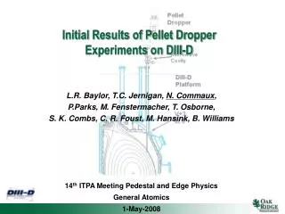
ELMs Triggered from Deuterium Pellets Injected into DIII-D and Extrapolation to ITER. L.R. Baylor 1 , T.C. Jernigan 1 , N. Commaux 1 , S. K. Combs 1 , P.B. Parks 2 , M. E. Fenstermacher 3 , T.E. Evans 2 , T. H. Osborne 2 , R.A. Moyer 4 , J. Yu 4

E N D
ELMs Triggered from Deuterium Pellets Injected into DIII-D and Extrapolation to ITER L.R. Baylor1, T.C. Jernigan1, N. Commaux1, S. K. Combs1, P.B. Parks2, M. E. Fenstermacher3, T.E. Evans2, T. H. Osborne2, R.A. Moyer4, J. Yu4 1Oak Ridge National Laboratory, Oak Ridge, TN, USA 2General Atomics, San Diego, CA, USA 3 Lawrence Livermore National Laboratory, Livermore, CA, USA 4University of California San Diego, San Diego, CA, USA Fueling of Magnetic Confinement Machines Hersonissos, Crete, Greece 16-17 June 2008
Overview • ITER has a potential significant ELM problem – erosion of divertor looks serious • Methods to mitigate the ELM problem have been proposed: • Pellet ELM pacing • Resonant magnetic perturbations • Pellets injected from all locations are known to trigger ELMs - Why??? • DIII-D Pellet Dropper Installed to Investigate ELM pace making • ELM pacing requirements for ITER are challenging • RMP suppresses ELMs on DIII-D, but at high density some ELMs return • Further research into pellets for ELM mitigation is ongoing also at JET and AUG.
Introduction to ELM Pacing Physics EdgeLocalizedMode: periodic instability located at the H-mode edge transport barrier • ELMs result from edge pressure clamped at ballooning limit – transient breakdowns of edge barrier – filaments are ejected from the plasma • Significant fraction of the total plasma stored energy ~5% can be expelled by an ELM (>10 MJ on ITER) • Significant erosion of plasma facing materials will occur for ELM bursts greater than 1 MJ.(A. Loarte, Nucl. Fusion47 No 6 (June 2007) S203-S263) • A method to eliminate or induce rapid small ELMs is badly needed for ITER. • Compatibility of method with pellet fueling needs to be demonstrated. Filaments evolving during ELM on MAST. ( Kirk, et al. PRL 2004. ) LRB Crete Jun2008
Size of ELM Loss Predicted for ITER as much as 20 MJ Loarte et al., Nuclear Fusion, ITER Physics Basis,Chapter 4 Minimum Acceptable Value (?) Full performance ITER plasma W pedestal can be as much as 100 MJ leading to ~20 MJ ELM loss if n*ped is the controlling parameter. LRB Crete Jun2008
CFC erosion is negligible forQELM < 0.5 MJ/m2[Zhitlukhin et al., JNM, 2007] Erosion of ITER Divertor Tiles ITER SOL projection on the divertor plates is 3.0 m2 ITER ELM size needs to be < 1.5 MJ for low erosion LRB Crete Jun2008
Overview LRB Crete Jun2008 • ITER has a potential significant ELM problem – erosion of divertor looks serious • Methods to mitigate the ELM problem have been proposed: • Pellet ELM pacing • Resonant magnetic perturbations • Pellets injected from all locations are known to trigger ELMs - Why??? • DIII-D Pellet Dropper Installed to Investigate ELM pace making • ELM pacing requirements for ITER are challenging • RMP suppresses ELMs on DIII-D, but at high density some ELMs return • Further research into pellets for ELM mitigation is ongoing also at JET and AUG.
) ) 2 2 - - 3.6 3.6 m m 14 14 3.2 3.2 Density Density (10 (10 2.8 2.8 L L e e n n 2.4 2.4 a a 1.2 1.2 D D .) .) 0.8 0.8 a.u a.u ( ( Divertor Divertor 0.4 0.4 0.0 0.0 2210 2210 2220 2220 2.21 2.22 2.23 2.24 2.25 3.11 3.11 3.12 3.12 3.13 3.13 3.14 3.14 Time (s) Time (s) Fueling Pellets Injected from all Locations on DIII-D Trigger ELMs DIII-D 99474 PoP 2000 Vertical LFS HFS DWtot ~ 8% DWtot ~ 4% DWtot ~ 1% 2.69 2.70 2.71 2.72 2.73 • Pellets injected from the 5 different injection locations on DIII-D are observed to trigger immediate ELMs. • LFS injected pellets trigger larger longer lasting Da perturbations (larger ELMs). LFS is more sensitive for ELM triggering. • Natural ELM frequency on DIII-D is higher than available pellet fueling frequency so no chance to test ELM pacing with fueling pellets. LRB Crete Jun2008
ne cs L Te qe L Pe L q f What Causes an ELM Trigger from a Pellet? • Pellet cloud releases from pellet and expands along a flux tube. • Density from the cloud expands along flux tube at the sound speed cs. • Temperature ‘cold wave’ travels along the flux tube at the thermal speed. Heat is absorbed in the cloud resulting in a temperature deficit far from the cloud. • Pressure decays and expands along the flux tube with a lower pressure far from the cloud. • Strong local cross field pressure gradients result along the flux tube that form on ms time scales. LRB Crete Jun2008
HFS Pellet Induced ELM Details from DIII-D ELM Triggered ELM End Pellet Da represents ablation of pellet in the plasma with assumed constant radial speed. DIII-D 129195 1.8mm pellet injected from inner wall is ~10% density perturbation 0.10 Pellet Enters Plasma TS profile time 0.08 Pellet Da 0.06 0.04 0.02 0.00 1.9 neL(1014m-2) 1.8 Divertor Da 1.7 1.6 1.5 80 60 dBr/dt (a.u.) Inner wall 40 No MHD precursor to pellet induced ELM 20 0 -20 -40 200 150 dBr/dt (a.u.) Outer shelf 100 50 0 -50 2773.0 2772.2 2772.4 2772.6 2772.8 Time (ms) • The ELM is triggered 0.05 ms after the pellet enters the plasma or 147 m/s* 0.05 ms = 7.4 mm penetration depth. LRB Crete Jun2008
Depth of Pellet when ELM is Triggered in DIII-D is Much Less Than Top of the Pedestal Electron Pressure Pedestal ITER Penetration Requirement 30 DIII-D 129195 2.772s Pre-pellet and ELM ASDEX-U Trigger Range 25 Non-RMP HFS RMP HFS Non-RMP LFS RMP LFS 20 Pe (kPa) 15 10 5 0 0.6 0.7 0.8 0.9 1 1.1 r Pellet Location when ELM Triggered LRB Crete Jun2008 • Data from DIII-D indicates that the pellet triggers an ELM before the pellet reaches half way up the pedestal. (% Ped is % of Te pedestal height) • Note: Pellets must penetrate deeper to trigger an ELM when RMP is applied. • ASDEX-U trigger range is deeper (G. Kocsis, et al,Nucl. Fusion 47 1166 (2007).)
Pellet ELM Pacing Led to 2X Higher ELM Frequency on AUG • Initial pellet ELM pacing shown for 1 second on AUG. (P. Lang, et al Nuc. Fusion, 2004). Small fueling pellets from HFS doubled the natural ELM frequency. • Further optimization needed to reduce strong fueling induced confinement decay and greatly increase the natural ELM frequency. LRB Crete Jun2008
Overview LRB Crete Jun2008 • ITER has a potential significant ELM problem – erosion of divertor looks serious • Methods to mitigate the ELM problem have been proposed: • Pellet ELM pacing • Resonant magnetic perturbations • Pellets injected from all locations are known to trigger ELMs - Why??? • DIII-D Pellet Dropper Installed to Investigate ELM pace making • ELM pacing requirements for ITER are challenging • RMP suppresses ELMs on DIII-D, but at high density some ELMs return • Further research into pellets for ELM mitigation is ongoing also at JET and AUG.
Pellet Dropper Microwave Cavity DIII-D Platform V+3 at 0o Pellet Dropper for ELM Pacing on DIII-D • The dropper was developed from existing equipment to make a simple ELM trigger tool. • It uses a batch extruder with pellet cutter to supply sub 1mm D2 pellets at up to 50 Hz for triggering ELMs on DIII-D • The extruder is cooled with a G-M cryocooler and LN2 for simplified installation and operation • Gravity acceleration limits pellet speeds to ~ 10 m/s • Low speed and small pellet size minimize fueling, but should make strong enough density perturbations to trigger ELMs LRB Crete Jun2008
Pellet Dropper Operation Pictures of extruded solid deuterium (14K) and pellet chopped from extrusion Data from microwave cavity showing mass of each pellet.
8.0 DIII-D 120775 1.0mm 10 m/s 7.0 1.2 6.0 1.8mm 200 m/s 1.0 5.0 Te (kev) 0.8 D ne (1019 m-3) 4.0 0.6 3.0 0.4 2.0 0.2 1.0 1.0mm 50 m/s 0.0 0.0 1.0 1.05 0.7 0.8 0.9 r Pellet Dropper Now Operational on DIII-D • NGS ablation model shows pellets should nearly reach Te pedestal in DIII-D H-mode. Good simulation of expected ITER 3mm pellet penetration depth. • Initial operation will be to determine penetration depth required to trigger ELMs. LRB Crete Jun2008
Target Plasma for the Pellet Dropper is the ITER Scenario DIII-D ITER Like Scenario Density ELMs of this size on ITER could be 15 MJ per ELM PNBI Divertor Da ORNL Filterscope Data The dropper is designed to drop 50 Hz pellets to trigger 50 Hz ELMs that have smaller energy loss Can the dropper be used to Obtain 5X increase in ELM Frequency? Wtot 1.0 3.0 4.0 2.0 0.0 E. Doyle 2008 Time (s) LRB Crete Jun2008
Pellet Dropper Diagnostic Views Dropper Pellet Trajectory Fast Camera Viewing Region • Fast camera at 90 degree midplane has an excellent view of the dropped pellets (and inner wall fueling pellets). (J. Yu, Phys Plasmas 15 (2008) 032504. ) • Filterscope Da views of the divertor and midplane are used to observe the pellet perturbations to the SOL. Visible bremsstrahlung and interferometer can also see some density perturbation. ITER Scenario Plasma Shape
NBI H-mode Z f Pellet Dropper Initial Results – April 2008 Ohmic L-mode • The 1-mm 10/ms deuterium pellets dropped during L-mode Ohmic plasmas travel in a vertical path and are observed in the divertor Da signals and edge interferometer. • In H-mode NBI plasmas the dropper pellets are observed to “skip” along the SOL and are swept toroidally. No interferometer signals for these pellets – no penetration inside the separatrix. • The largest pellets appear to coincide with ELMs and there may be a cause and effect, which is under investigation. • Drag and fast ion ablation in the SOL are candidates for the strong toroidal deflection and poor penetration. • Pellets with more momentum normal to the plasma are needed with this vertical trajectory. Tangential view from fast framing camera – images and movies by J. Yu LRB Crete Jun2008
NBI H-mode Z f What Causes the Toroidal Defection? • Plasma flow in the SOL is measured by CER to be ~ 10 km/s. • Drag estimated from Fd = -1/2 r v2 Cd using Cd = 0.1 for a sphere yields a deflection of only ~ 1cm • NBI was in the co direction yielding fast ions that have trapped orbits into the SOL • Toroidal Force on the pellet is on the order of 1 m-Nt • On the order of 1011 fast ions (80 keV) giving up 10% of their energy to the pellet could explain this defection. • A counter NBI experiment is needed to verify this hypothesis. LRB Crete Jun2008
ELM Frequency Increase Due to pellets ? 2.0 Shot 132650 Dropper pellets 1.0 ECRH Density (1019 m-3) 0.0 5 Divertor D (a.u.) 4 3 2 1 0 8 PNBI (MW) 4 0 2 2.5 3 3.5 4 4.5 time (s) • Dropper pellets injected during ECRH pedestal control experiments : • The ELM frequency is higher (~40 Hz) than without the pellets (~10 Hz) LRB Crete Jun2008
Pellet Dropper Microwave Cavity DIII-D Platform V+3 at 0o Pellet Dropper Future Plans for DIII-D • The low pellet speed at a glancing angle to the plasma edge limits the effectiveness in triggering ELMs. (No obvious proof of increase in the ELM frequency) • The plan is to modify the entry tube to deflect the pellets so they hit more normal to the plasma surface. • Less SOL to travel through • Higher momentum normal to the plasma. Speed normal to plasma surface to be 10 m/s instead of present 3.5 m/s. • Future modifications as necessary to obtain reliable ELM trigger in the ITER scenario plasma – larger pellets and/or faster. LFS trajectory as planned for ITER. LRB Crete Jun2008
Overview LRB Crete Jun2008 • ITER has a potential significant ELM problem – erosion of divertor looks serious • Methods to mitigate the ELM problem have been proposed: • Pellet ELM pacing • Resonant magnetic perturbations • Pellets injected from all locations are known to trigger ELMs - Why??? • DIII-D Pellet Dropper Installed to Investigate ELM pace making • ELM pacing requirements for ITER are challenging • RMP suppresses ELMs on DIII-D, but at high density some ELMs return • Further research into pellets for ELM mitigation is ongoing also at JET and AUG.
Challenge of ITER Pellet Fueling and ELM Pacing • ITER will have 2 pellet injectors that each provide D2, DT, T2 pellets (5mm @ ~10Hz, 3mm @ ~30Hz). • Inside wall pellet injection for efficient fueling beyond the pedestal utilizing a curved guide tube. Maximum pellet survival speed is 300 m/s. • Pellet injector must operate for up to 1 hour continuously and produce ~ 1.5 cm3/s (0.3 g/s) of ice. • A LFS tube is being added for pellet ELM pacing. Pellet speed maximum probably ~500 m/s. • Pellet pacing projected to require 3-4mm size pellets at 20-40 Hz. (A.Polevoi, ITER 2007 DCR) Pellet Path in ITER LRB Crete Jun2008
Pellet Normalized Throughput in Present Experiments is Heading Toward Projected ITER Pellet ELM Pacing Conditions 10 DIII-D JET AUG 8 JT-60U ITER 6 Pellet Throughput/Plasma Volume (mm3/s-m3) ITER range covers: 3mm@20Hz – 4mm@40Hz 4 2 0 0.0 0.1 0.2 0.3 0.4 0.5 0.6 0.7 t (Time between pellets / tE) 1/ E fpel • The normalized pellet throughput from current pacing and fueling experiments is far from the projected operating point. • The planned pellet ELM pacing experiments on JET, DIII-D, and ASDEX-U are all planning to be in a regime that is more ITER relevant in terms of normalized throughput and time between pellets scaled to energy confinement time. LRB Crete Jun2008
Pellet Convective Loss of Energy Must be Low to Maintain Good Confinement During ELM Pacing Pellet Density Perturbation with no Drift • The planned low field side pellets for ELM pacing on ITER are expected to have shallow penetration. • Drift of pellet mass due to curvature and ÑBis expected to expel nearly all of the pellet particles. • Calculation of the pellet cloudlet reheating during the drift process with PRL+PELLET code shows the entire cloud drifts out after reheating to < 100 eV. (Parks and Baylor, PRL 94 (2005) 125002.) • The total convective loss for the 3mm pellet is 4 kJ and 8 kJ for the 4mm pellet. At 40 Hz this is less than 0.5 MW of convective pellet loss. • LFS pellet triggered ELM on D3D has same DW as natural ELM in same plasma. Resulting Deposition Cloudlet Drift Ablation (No drift) Dne r 0.9 1.0 LRB Crete Jun2008
Overview LRB Crete Jun2008 • ITER has a potential significant ELM problem – erosion of divertor looks serious • Methods to mitigate the ELM problem have been proposed: • Pellet ELM pacing • Resonant magnetic perturbations • Pellets injected from all locations are known to trigger ELMs - Why??? • DIII-D Pellet Dropper Installed to Investigate ELM pace making • ELM pacing requirements for ITER are challenging • RMP suppresses ELMs on DIII-D, but at high density some ELMs return • Further research into pellets for ELM mitigation is ongoing also at JET and ASDEX-U.
Resonant Magnetic Perturbation Evans, NF2008 • RMP created by currents in external coils (I-coil on DIII-D) and results in stochastic magnetic fields in the plasma edge that affect the plasma edge profiles and can keep the edge pressure below the ballooning limit. LRB Crete Jun2008
RMP Using Internal Coils is Successful at Eliminating ELMs DIII-D RMP and non-RMP Comparison • RMP technique developed is successful in ITER like collisionality and shape at eliminating ELMs. (T. Evans, et al.Nucl. Fusion 48 (2008) 45009). LRB Crete Jun2008
6 10 Hz 1.8mm Pellets Density (1013 m-3) 131467 Density (1013 m-3) 129754 3 5 Hz 1.8mm Pellets 0 0 Full ELM Suppression ELMs ~0.5 DW from pre-RMP Divertor Da (a.u) 8 131467 6 4 2 0 Partial ELM Suppression 0.8 Divertor Da (a.u) 0.6 129754 0.4 0.2 0.0 0.0 0 Icoil (kA) -6.0 0.0 4.0 5.0 5.0 3.0 1.0 2.0 Time (s) Pellet Fueling During RMP Can Lead to Some ELM Activity • HFS Pellet Fueling (and gas fueling) into RMP ELM suppressed plasmas can lead to a return to ELMs when high density is reached. • Two examples with 5 Hz and 10 Hz 1.8mm HFS pellets are shown. The case with fully suppressed ELMs before the pellets actually has more ELM activity with the pellet fueling. • These results indicate that further optimization of RMP is needed for high density operation.
Pellets in RMP ELM-free H-Mode Trigger ELM Like Events -2.5*10 5.7*10 7.7*10 1.9*10 3.8*10 -5.0*10 -5.0*10 1.0*10 1.5*10 5.0*10 1.0*10 1.5*10 5.0*10 -0.78 -6000 -4000 -2000 2.10 3.55 4.99 2000 0.66 0 0 0 13 13 13 13 11 5 6 5 6 6 7 6 7 iu30 129194 pnbi 129194 phd02f 129194 density 129194 WMHD 129194 2000 2500 3000 3500 4000 4500 Fri Jan 25 07:06:38 2008 DIII-D 129194 neL(1014m-2) PNBI(MW) -4.4 kA Icoil(kA) 1.5 1.0 0.5 WMHD (MJ) 0.0 ITER Similar Shape Divertor Da Time (s) 3.0 4.0 2.0 • Pellet induces an immediate small ELM and some subsequent ELMs. Expanded view of this pellet LRB Crete Jun2008
Pellets in RMP ELM-free H-Mode Trigger Small Immediate ELM Like Events 2.0 DIII-D 129194 1.0 neL(1014m-2) 0.0 17.0 ELM 12.0 Pellet Da 7.0 2.0 110 dBr/dt (a.u.) Outer shelf 70 30 -10 1.20 ~4% DW WMHD (MJ) 1.10 1.00 ITER Similar Shape 16 12 Divertor Da 8 4 Time (s) 3.260 3.270 3.290 3.280 • Pellet induces an immediate ELM, but much smaller stored energy decrease than occurs with a larger ELM 20ms later. • Further optimization needed to eliminate ELMs altogether. LRB Crete Jun2008
Summary LRB Crete Jun2008 • ELMs are triggered by fueling pellets on DIII-D by the time the pellet reaches half way up the pressure pedestal. • Pellet dropper pellets velocity normal to the plasma is too low to penetrate through the SOL and trigger ELMs reliably. • A change in trajectory is planned and will be used for future pacing studies. • RMP for ELM suppression has been tested with pellet fueling and is found to have some ELM activity with the increased density • Needs further optimization to be compatible with high density operation and pellet fueling. • Fueling pellets also lead to ELMs in QH-mode (Baylor, et al., JNM 2005) • The pellet injection system for ITER ELM pacing presents challenges for the technology in throughput and reliability, gas gun concept looks promising • Tests of convective losses and high repetition rate pellets needed to project to ITER • Extruder and accelerator prototypes will be produced which can be available to test on existing tokamak devices
Plans for Future R&D LRB Crete Jun2008 • ELM triggering with vertical pellets on DIII-D – test pellet size and speed normal to the plasma necessary to trigger ELMs. • Investigate ELM size and confinement properties with pellet pacing > 5x natural ELM frequency • Compare DIII-D and JET pellet ELM pacing experiments • New JET pellet injection system utilizes ORNL pellet mass and cloud diagnostics • LFS pellets enter through the RF antenna, interesting coupling effects • Scaling of results to ITER and development of a 3D model for pellet ELM triggering • Future possible upgrade of D3DPI to use high frequency pellets with similar guide tube to ITER – test of newly developed technology for ITER
Pellet Throughput in Present Experiments Well Below That Projected for ITER Pellet ELM Pacing 5 DIII-D JET 4 AUG JT-60U ITER Pellet Size (mm) 3 Higher Throughput 2 1 0 0 20 40 60 80 100 Pellet Frequency (Hz) • The anticipated pellet throughput for ITER pellet ELM pacing is well above that in present day experiments. (Technically challenging) • A multi-barrel injection system is likely needed to meet this high ITER throughput requirement. (Pellet sizes are cylindrical equivalent) LRB Crete Jun2008
Pellet Throughput in Present Experiments Well Below That Projected for ITER Pellet ELM Pacing * - Future • The anticipated pellet throughput for ITER pellet ELM pacing is well above that in present day experiments. (Technically challenging) • A multi-barrel injection system is likely needed to meet this high ITER throughput requirement. (Pellet sizes are cylindrical equivalent) LRB Crete Jun2008