Download
1 / 28
280 likes | 532 Views
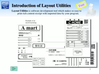
Introduction and Principles of Layout and Line Design presented by Nilesh arora - a founder of AddValue Consulting Inc. Find details of P.Q. analysis, Functional vs. Process layout and number of lines etc.

E N D
“Layout and Line Design” by Best Performing Consulting Organization AddingValueInTotality!!
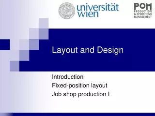
Introduction; P.Q. analysis; Process graph and time estimate; Functional vs. Process layout and number of lines; One Piece Flow lines; Large vs Small Lines; Takt time; Shojinka and multiskilled operators; Small in line machines; Line balancing; Workstation design. 20 principles of Layout and Line Design. I. Production Flow I.1. Layout and Line Design 5. Low Cost Automation 4. Smed 3. Standard Work 2. Border of Line • Layout and Line Design
Introduction • It is important to differentiate between PROCESS and OPERATION: • PROCESS is flow (movement) of materials from dock to dock. It includes many operations: • Material transportation; • Material waiting batch size end; • Material transformation; • Material batch waiting; • Material being inspected. • OPERATION is flow of operator movements to perform above operations; • TARGETS of Layout and Line Design: • Elimination of operations other than Value Added; • Creation of 1 piece flow value added operations.
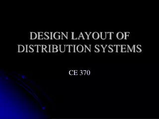
Layout and Line Design always starts with a PQ analysis; The A references (high runners) are good candidates for semi automated lines (maintaining 1 piece flow); The B references are good candidates for manual, less automated lines; The C references (low runners) are good candidates for single bench/manual lines, flexible for many references. P.Q. analysis • 3 references = 45% of the quantity sold in 1 year • 10 references = 35% of the quantity sold in 1 year Q: Quantity A1 • 15 references = 15% of the quantity sold in 1 year A2 (3 ref) (10) • 120 references = 5% of the quantity sold in 1 year B (15) C (120) P: Product References
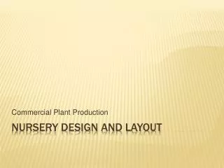
It should be done for each A (high runners) reference; Starts with the main component (the one where all the others will be agregated, the grey body). Ex: the chassis of an automobile; No representation of Muda operations (only value added operations); Time should be estimated without Muda (net operation times); At this stage times represent a rough estimate of net operation times (be carefull with standard times given by time study departments, usually include too much Muda). Tubes Blue Disk Screws Grey Body P1 Wings 16 s P2 4 s M1 6 s M2 3 s Central screw M3 12 s Wing screws. M4 16 s Cone M5 3 s Final screw M6 25 s Assembled Plug Process Graph and Time Estimate • A Process graph represents a possible order of assembly or production; • 3 types of information: • Blue: components; • Yellow: value added operations; • Green: times.
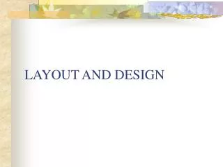
Functional vs Process Layout Functional Functional Layout Layout Big Big Batch Batch Production Production Assembly Assembly Sub Sub Assembly Assembly Control Control W W A A R R E E H H O O U U S S E E Work Work in in Process Process Waiting Waiting
Functional vs Process Layout Line Layout Small Batch Production WAREHOUSE Assembly Sub Assembly Control Material Flow
One Piece Flow Lines Cell Layout One Piece Production Pack Control Material Flow Supermarket Sub Assembly Assembly
One Piece Flow Lines Layout before Kaizen Layout after Kaizen Results Before After Lead Time Cycle Time Workers Flexible WIP Area Productivity
Transport distance = 28 m One Piece Flow Lines Situation Before Kaizen (very poor FTQ/Efficiency) Situation After Kaizen (excellent FTQ/Efficiency)
Functional vs Process Layout • The evolution of a Functional Layout (job shop type) to a Process Layout (flow shop type) at a Kawasaki Motorcycle machining plant; • Step 1: one operator for each isolated machine; • Step 2: one operator for 2/3 machines; • Step 3: process flow cells; • Step 4: process flow cells in-line and multi cell operators
Functional vs Process Layout • Aluminium Die Casting plant; • From a Functional Layout to ... • ...Process Flow Layout... • Check the savings in material flow (lines).
Functional vs Process Layout Product vs Process Matrix Operations 1 2 3 4 5 6 7 A X X X X X X Possible product family for 1 process flow line design B X X X X X X X C X X X X X X A Product References D X X X X E X X X X F X X X X • Make a Process Graph for each of the A references; • Check the Product vs Process matrix to group similar Process Products; • After, check B and C references (for the best fit within A families or stand alone benches/lines).
Large vs. Small Lines • Small number of product references flow on 1 or more automated lines (Low Cost Automation); • Large number of product references flow on 1 or more smaller less automated lines.
Available Time for Production (1) Customer Demand (2) Takt Time = Example: Time: 2 x 8 h (480 min) Breaks: 20 minutes / shift Takt time = Cleaning: 10 minutes / shift Demand: 10.000 units/week = 0,45 min = 27 sec /unit 2 x (480-20-10) 10.000 / 5 Takt Time • The production cycle should obey the Takt Time, i.e., match the demand cycle; • Usually the Line Design Cycle Time is smaller than the Takt Time (because of Efficiency Losses). (1) Total Time without programmed stoppages. (2) Number of units required in that period of time.
Shojinka and Multiskilled Operators • Shojinka = line is able to adapt output to Takt Time by changing nº of operators
6 6 1 2 3 4 5 1 2 3 4 5 7 8 7 8 1B 2B 3B 1B 2B 3B Shojinka and Multiskilled Operators • 2 operators cell. • “Daisy” Line Design: • Operators work together in a common area; • Operators don´t work inside isolated islands (with machines between); • Machine Input and output position are side by side (this implies new machine designs); • Automation is separated from manual work. • 3 operators cell. • Multiskilled operators: • Supervisors are responsible for developing Multiskilled operators; • Supervisors must be skilled in JI – Job Instruction training; • Train operators using Training Plans and Breakdown Sheets.
Small In-line Machines • To change a Functional Layout to a Process based Layout, usually more machines are necessary; • The “Small In-Line Machines” concept refers to smaller less universal machines; • It is possible to develop this type of machines in-house; • Usual in-house developed machines are; • Cleaning and rinsing machines; • Simple machining operations; • Small presses; • Use oil pans for cleansing; • Use hair dryers and home use ovens for drying and heating. • Looking at a universal automated centralized machine, the Kaizen eye tries to spot: • What are the real value added operations done inside the machine; • How can the machine be simplified to fit a one piece flow line. High Speed Machines Small In-line Machines Parts feeder
Line Balancing Product Work Contet Work Team A (Regular Team) Work Team B (“Mura” Team) A B Product Families C • Responsible to operate a fixed number of operations in-line; • Line balancing based on product family C Work Content; • Constant workload, independent from product mix. • Responsible for off-line work ,or; • Responsible for variable operations (Mura); • Made up of fewer workers; • Made up of most skilled wokers (work load varies according to product mix).
«Mura» concentrated WS (workstations) Line Takt = Operator Takt Time (sec) A B C A B C A B C Operator 1 Operator 2 Operator 3 Line Balancing «Mura» is spread all over the line = Operator Stress = «Muda» Line Takt = Average Operator Takt Time (sec) A B C A B C A B C Operator 1 Operator 2 Operator 3
Tubes Blue Disk Screws Grey Body P1 Wings 16 s P2 4 s M1 6 s M2 3 s Central screw M3 12 s Wing screws. M4 16 s Cone M5 3 s Final screw M6 25 s Assembled Plug Line Balancing • Balance operations using the process graph: • Workstation 1: P1+M1+P2+M2 = 29 seg • Workstation 2: M3+M4 = 28 seg • Workstation 3: M5+M6 = 28 seg • Start on top of the graph (main component); • 1st operation is P1 because is the 1st subassembly to go into the main component; • Use “Balancing Charts” with magnets (yamazumi chart), in case of many operations; • Use Excell worksheets.
Many Muda of operator movement due to bad placement of containers; • No fixed location for containers; • Containers not prepared for frontal supply; • No 5 S. • All components at operator's arm reach; • Small containers and two bin system with frontal supply; • Empty bin exit place (2nd level); • 5 S. Waste Hole Waste Bin Workstation Design
Design the lines based on the types, volumes and life cycle of the products 2. Design small in-line equipment that can be moved around easily 3. Take into account the takt time of the customers 4. Make a 1 piece flow in the processing order 5. Say “No” to MUDA of transport. Minimize use of conveyors 20 Principles of Layout and Line Design
12. Work should flow from right to left (anti clock wise) 6. Design set-up time with Zero as a target 7. No isolated operator islands should be allowed 8. Separate man work from machine work 9. Combine entrance and exit of work pieces 10. Equipment should have a narrow width 11. Put only necessary materials within arms length 20 Principles of Layout and Line Design
13. Karakuri: subtle maneuverability is important 14. Lower the speed as much as possible 15. Machines should stop when abnormality occurs 16. Mechanical approach preferred to electrical approach 17. Do not automate parts supply without careful study 18. Do not process several part simultaneously 19. Simulate new equipment before installation 20. Organize layout by process and keep walls free 20 Principles of Layout and Line Design
ADDVALUE Services VALUE ADDED COACHING-VAC® BUSINESS COACHING LIFE COACHING Operation Excellence Counselling Team Excellence Therapy AddingValueInTotality!! Business Excellence Astrology
AddValue at a glance Best Performing Consulting Organization Business Coaching Life Coaching