
Fundamental Principles of Circuit Analysis: Ohm's Law and Nodal Analysis
E N D
Presentation Transcript
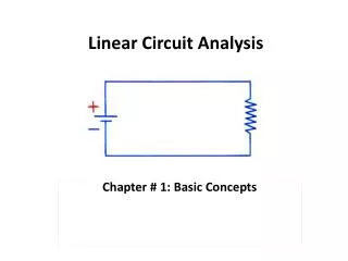
Systematic Circuit Analysis Nodal Analysis Chapter 4 Section 1
3 Fundamental Principles • Ohm’s Law • V = I · R, where I enters at the higher voltage side • Kirchoff’s Voltage Law • Algebraic sum of voltages around a loop equal zero • Kirchoff’s Current Law • Algebraic sum of currents entering and leaving a node equal zero
Circuit Simplification • Series Resistors can be combined into a single equivalent resistance • Parallel Resistors can be combined into a single equivalent resistance • Current sources in parallel add algebraically • Voltage sources in series add algebraically • A voltage source is series with a resistor can be replaced by a current source in parallel or vice versa
Shortcuts • Voltage Divider – a voltage dividing across a series combination of resistors • Largest voltage is across the largest resistor • Current Divider – a current dividing among a parallel combination of resistors • Largest current is through the smallest resistor
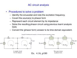
Nodal Analysis • Employs the 3 fundamental laws • May not require any circuit simplification • Consists of a straight-forward step-by-step procedure • Involves the solution of a set of linear equations simultaneously • Used by most circuit analysis computer programs like PSpice
Example • Find the voltages and currents
Step One • Identify all nodes that have at least 3 components connected to them • Choose one of the above nodes as the ground, or reference node, Vo=0 volts • Label the other nodes with V1, V2, etc.
Voltage Notation • Remember that voltage is always measured with respect to some other point • So V1 the voltage at node 1 minus the voltage at node 0, or V1-Vo = V10 = V1 • V12 would be the voltage at node 1 minus the voltage at node 2, or V12 = V1-V2
Voltage Notation • V12 could also be obtained by going through any path, say node 3 • V12 = V132 where V132 = V13 + V32 • But V13 + V32 = (V1-V3) + (V3-V2) • And (V1-V3) + (V3-V2) = V1-V2 = V12
Circuit After Step One V1 Vo = 0 volts
Step Two • Choose currents for every circuit branch that is connected to any of the unknown voltage nodes • In this circuit, choose currents for the branches connected to V1 • You can also label voltages at other nodes in the circuit (nodes that have only two components), Va and Vb
Circuit after Step Two I1 + - I3 + - V1 Vb Va + I2 - Vo = 0 volts
Step Three • Find the value of each current or find an expression for each current in terms of the unknown voltages, V1, V2, etc. • The idea is to get all the currents to be expressed in terms of the node voltages, so that a KCL equation can be written at each unknown node, giving us as many equations as unknowns
Step Three • If you have a resistor between two nodes, then the current is the voltage at the node where the current originates minus the voltage at the other node divided by the resistance (Ohm’s Law) • For this circuit the 10Ω resistor is between nodes 1 and ground (node 0) • I2 = (V1 – 0) / 10Ω = V1 / 10Ω
Step Three Cont. • If you have a resistor and a series voltage source between two key nodes, determine the voltage at the node between the components and then use Ohm’s law • There is a 6v source and 14Ω resistor in series between node 1 and ground • Va = Vo+6v. = 6v. • I1 = (Va - V1) / 14Ω = (6v - V1) / 14Ω
Step Three Cont. • There is also 5v source and 10Ω resistor in series between node 1 and ground • Determine the voltage at the intermediate node • Vb = Vo+5v. = 5v. • Use Ohm’s law to determine the current • I3 = (V1-Vb) / 14Ω = (V1-5v) / 10Ω
Circuit after Step Three I1=(6-V1)/14Ω + - I3=(V1-5)/10Ω + - V1 Vb=5v Va=6v + I2 = V1/10Ω - Vo = 0 volts
Step 4 • Write Kirchoff’s Current Law at each node with an unknown voltage • I1 =I2 +I3 • Substitute each value or expression into each KCL equation • (6v-V1)/14Ω = V1/10Ω + (V1-5v)/10Ω
Step 5 Solve • Solve the set of equations for each unknown voltage • (6v-V1)/14Ω = V1/10Ω + (V1-5v)/10Ω • Multiply both sides to clear fractions • 70Ω·[(6v-V1)/14Ω = V1/10Ω + (V1-5v)/10Ω] • 30v - 5·V1= 7·V1 + 7·V1 - 35v • Group like terms and solve • 65v = 19·V1 or V1 = 3.42v
Step 5 Solve Cont. • Since V1 = 3.42v • Find each current by substituting the voltage values found into each current equation as appropriate • I1 = (6v-V1)/14Ω = (6-3.42)/14 = .184 A • I2 = V1/10Ω = 3.42/10 = .342 A • I3 = (V1-5v)/10Ω = (3.42-5)/10 = -.158 A
Step 6 – Reality Check I1=.184A + - I3= -.158A + - V1=3.42v Vb=5v Va=6v + I2= .342A - Vo = 0 volts
Example with a Dependent Source • Find the voltages and currents I1
Handling the Dependent Source • The dependent source will be dependent on some voltage or current in the circuit • You will need to express that voltage or current in terms of the unknown node voltages • The idea is to only use the node voltages in finding the currents so that there will be as many KCL equations as variables
Step One • Identify all nodes that have at least 3 components connected to them • Choose one of the above nodes as the ground, or reference node at zero volts • Label the other nodes with V1, V2, etc.
Circuit after Step 1 I1 V1 Vo = 0 volts
Step Two • Choose currents for every circuit branch that are connected to any of the unknown key voltage nodes
Circuit after Step 2 I1 + - V1 Vb + I2 - - I3 + Vo = 0 volts
Step Three • Find the value of each current or find an expression for each current in terms of the unknown voltages, V1, V2, etc. • If you have a resistor between two nodes, then the current is the voltage at the node where the current originates minus the voltage at the other node divided by the resistance (Ohm’s Law) • I2 = (V1 – 0) / 4Ω = V1 / 4Ω
Step Three Cont. • If you have a resistor and a series voltage source between two nodes, determine the voltage at the node between the components and then use Ohm’s law • Vb = Vo+3v. = 3v. • I1 = (V1-Vb) / 2Ω = (V1-3v) / 2Ω
Step Three Cont. • If you have multiple resistors and/or voltage sources between two key nodes, combine them together to get one resistor and one source • If there is a dependent part of the source, express it in terms of the unknown node voltages • Determine the voltage at the node between the equivalent resistor and source • Use Ohm’s law
Circuit for Step 3 I1 + - V1 Vb=3v Vb Va 5v + 4Ω·I1 + I2 - - I3 + Vo = 0 volts
Step Three Cont. • The combined dependent source is 5v+4Ω·I1 • So Va = V1 – (5v+4Ω·I1) • But I1 in the dependent source was determined to be (V1-3v)/2Ω • So Va = V1–(5v + 4Ω·(V1-3v)/2Ω) = -V1+1 • I3 = (Vo-Va) / 4Ω = (0-(-V1+1)) / 4Ω • I3 = (V1 -1v) / 4Ω
Circuit for Step 4 I1=(V1-3)/2Ω + - Va= 1v-V1 V1 Vb=3v Vb 5v + 4Ω·I1 + I2= V1/2Ω - - + I3=(V1-1)/4Ω Vo = 0 volts
Step 4 • Write Kirchoff’s Current Law at each node with an unknown voltage • I3 =I2 +I1 • Substitute each value or expression into each KCL equation • (V1 -1v) / 4Ω = V1 / 4Ω + (V1-3v) / 2Ω
Step 5 Solve • Solve the set of equations for each unknown voltage • (V1 -1v) / 4Ω = V1 / 4Ω + (V1-3v) / 2Ω • Multiply both sides to clear fractions • 4Ω·[(V1 -1v) / 4Ω = V1 / 4Ω + (V1-3v) / 2Ω] • V1 - 1v= V1 + 2·(V1-3v) • Group like terms and solve • 5v = 2·V1 or V1 = 2.5v
Step 5 Solving for Currents • Finding each current: • I3 =(V1 -1v) / 4Ω = (2.5v -1v) / 4Ω = .375 A • I2 =V1 / 4Ω = 2.5v / 4Ω = .625 A • I1 = (V1-3v) / 2Ω = (2.5v-3v) / 2Ω = -.25 A
Step 6 - Checking I1= -.25A + - Va= 1v-V1= -1.5v V1=2.5v Vb=3v Vb 5v+4Ω·I1=4v + I2= .625A - - + I3=.375A Vo = 0 volts
Class Activity • Find the current equations at node 1
Class Activity • Find I2 in terms of V1 • For a resistor between nodes, use Ohm’s law • Add polarities if not shown (+ at V1, - at V0) • I2 = V1/60Ω + _
Class Activity • Find I3 in terms of its value • For a current source between nodes, the current is fixed by the source • I3 = 2 A
Class Activity • Find I4 in terms of V1 • If you have series resistors, combine them and then use Ohm’s law • I4 = V1/(30+70)Ω = V1/(100Ω) + _ + _
Class Activity • Find I1 in terms of V1 • Combine series resistors, even if not next to each other, then find the voltage between the source and equivalent resistance
Finding I1 + - Va=100v V1 + - V1 100+80=180Ω Vo=0v Vo=0v So I1 = (Va-V1)/180Ω = (100-V1)/180Ω
Class Activity • Find I5 in terms of V1 • The voltage on the right side of the 50Ω resistor is known, because of the 150v source • I5 = (V1-150v) / 50Ω + -
Class Activity • Write KCL equation at node 1 • I1 + I3 = I2 + I4 + I5 Substitute all the current equations: • (100-V1)/180+2A=V1/60+V1/100+(V1-150v)/50
Class Activity (100-V1)/180+2A=V1/60+V1/100+(V1-150v)/50 Multiply both sides by 9000Ω: 5000-50V1+18000=150V1+90V1+180V1-27000 Group: 50000 = 470V1 Solve: V1= 106.4 v
Class Activity Checking I1=-.036A, I2=1.773A, I3=2A, I4=1.064A, I5=-.872A I1+I3=-.036+2 =1.964 A I2+I4+I5 = 1.773+1.064-.872 = 1.965 A – Yes!
Example with 3 Unknown Nodes • Find Voltages and Currents
Steps 1 & 2 • Find key nodes, assign one to ground, choose currents in branches I1 + - I2 V3 V1 I3 V2 + - Va + - + - I5 + - I4 Vo=0 volts
Step 3 – Current Equations • Currents for resistors between nodes • I1=(V1-V3)/4Ω • I3=(V2-V3)/7Ω • I4=V2/1Ω • I5= V3/5Ω • Resistor and source between nodes • Va = V1+ 9v • I2 = (Va-V2)/3Ω = (V1+9v-V2)/3Ω