Download

1 / 35
360 likes | 564 Views
Circuit Analysis III. Section 06. Linearity and Superposition. Linearity. Basically, a mathematical equation is said to be linear if the following properties hold. homogenity additivity. 1. Basic Electric Circuits. Linearity :. Many of us were brought-up to think that if plotting

E N D
Circuit Analysis III Section 06
Linearity Basically, a mathematical equation is said to be linear if the following properties hold. • homogenity • additivity 1
Basic Electric Circuits Linearity : Many of us were brought-up to think that if plotting an equation yields a straight line, then the equation is linear. From the following illustrations we have; 5
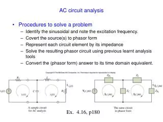
Using Linearity The procedure can be made entirely algorithmic 1. Give to Vo any arbitrary value (e.g., V’out =1 ) 2. Compute the resulting source value and call it V’_s 3. Use linearity. This is a nice little tool for special problems. Normally when there is only one source and when in our judgement solving the problem backwards is actually easier Assume that the answer is known. Can we Compute the input in a very easy way ?!! If Vout is given then V1 can be computed using an inverse voltage divider. … And Vs using a second voltage divider Solve now for the variable Vout
Basic Electric Circuits Linearity : Example: Given the circuit shown in Figure. Use the concept of linearity to find the current I0. Figure 9.1: Circuit for Example 9.1. Assume I0 = 1 A. Work back to find that this gives VS = 45 V. But since VS = 90 V this means the true I0 = 2 A. 9
Basic Electric Circuits Linearity : Example 9.2: In the circuit shown below it is known that I0 = 4 A when IS = 6 A. Find I0 when IS = 18 A. Figure 9.2: Circuit for Example 9.2 Since I0 = 4A IS = 6A and, I0 = X Is = 18A So, I0= 12A 10
Source Superposition This technique is a direct application of linearity. It is normally useful when the circuit has only a few sources.
Circuit with voltage source set to zero (SHORT CIRCUITED) SOURCE SUPERPOSITION = Circuit with current source set to zero(OPEN) Due to the linearity of the models we must have Principle of Source Superposition + The approach will be useful if solving the two circuits is simpler, or more convenient, than solving a circuit with two sources We can have any combination of sources. And we can partition any way we find convenient
SOURCE SUPERPOSITION • The Superposition Theorem states that a circuit can be analyzed with only one source of power at a time, the corresponding component voltages and currents algebraically added to find out what they'll do with all power sources in effect. • To negate all but one power source for analysis, replace any source of voltage (batteries) with a wire; replace any current source with an open (break).
look at to the following circuit and apply Superposition Theorem : Since we have two sources of power in this circuit, we will have to calculate two sets of values one for the circuit with only the 28 volt battery in effect. and one for the circuit with only the 7 volt battery in effect: .
Analyzing the circuit with only the 28 volt battery, we obtain the following values for voltage and current: Analyzing the circuit with only the 7 volt battery, we obtain another set of values for voltage and current:
Applying these superimposed voltage figures to the circuit, the end result looks something like this: Currents add up algebraically as well:
Basic Electric Circuits Superposition:Example 9.4. Given the circuit below. Find the current I by using superposition. Figure 9.5: Circuit for Example 9.4. First, deactivate the source IS and find I in the 6 resistor. Second, deactivate the source VS and find I in the 6 resistor. Sum the two currents for the total current. 19
Basic Electric Circuits Superposition:Example 9.4. Given the circuit below. Find the current I by using superposition. IVs = 3 A 20
Basic Electric Circuits Superposition:Example 9.4. Given the circuit below. Find the current I by using superposition. Total current I: I = IS + Ivs = 5 A 21
i Rs + + v V0 _ _ Thevenin and Norton Equivalent Circuits M. Leon Thévenin (1857-1926), published his famous theorem in 1883. Fig.2.17 (a) Thevenin equivalent circuit
Thevenin & Norton Equivalent Circuits • Thevenin's Theorem states that it is possible to simplify any linear circuit, no matter how complex, to an equivalent circuit with just a single voltage source and series resistance connected to a load. A series combination of Thevenin equivalent voltage source V0 and Thevenin equivalent resistance Rs
RTh VTh Resistive Circuit Thévenin Equivalent Circuit Thévenin’s Theorem: A resistive circuit can be represented by one voltage source and one resistor:
Calculating the equivalent Thevenin source voltage and series resistance is actually quite easy. First, the chosen load resistor is removed from the original circuit, replaced with a break (open circuit): Next, the voltage between the two points where the load resistor used to be attached is determined.
To find the Thevenin series resistance for our equivalent circuit, we need to take the original circuit (with the load resistor still removed), remove the power sources (in the same style as we did with the Superposition Theorem: voltage sources replaced with wires and current sources replaced with breaks), and figure the resistance from one load terminal to the other:
Thevenin's Theorem is a way to reduce a network to an equivalent circuit composed of a single voltage source, series resistance, and series load. Steps to follow for Thevenin's Theorem: (1) Find the Thevenin source voltage by removing the load resistor from the original circuit and calculating voltage across the open connection points where the load resistor used to be. (2) Find the Thevenin resistance by removing all power sources in the original circuit (voltage sources shorted and current sources open) and calculating total resistance between the open connection points. (3) Draw the Thevenin equivalent circuit, with the Thevenin voltage source in series with the Thevenin resistance. The load resistor re-attaches between the two open points of the equivalent circuit. (4) Analyze voltage and current for the load resistor following the rules for series circuits.
Thévenin’s Theorem – example 1 • Replace everything except the load resistor R with its Thévenin equivalent
“PART B” LEARNING BY DOING
Source Transformations • The Thévenin and Norton equivalent circuits both represent the same circuit • They have the same voltage-current characteristics
Using Source Transformations in Circuit Analysis • Any voltage source in series with a resistance can be modeled as a current source in parallel with the same resistance and vice-versa
EXAMPLE: SOLVE BY SOURCE TRANSFORMATION In between the terminals we connect a current source and a resistance in parallel The equivalent current source will have the value 12V/3k The 3k and the 6k resistors now are in parallel and can be combined In between the terminals we connect a voltage source in series with the resistor The equivalent source has value 4mA*2k The 2k and the 2k resistor become connected in series and can be combined After the transformation the sources can be combined The equivalent current source has value 8V/4k and the combined current source has value 4mA Options at this point 1. Do another source transformation and get a single loop circuit 2. Use current divider to compute I_0 and then compute V_0 using Ohm’s law
HomeWork Q. Find I3 using superposition theorm? I3
Source Transformation – Homework • Use source transformations to determine the voltage v
HomeworkUsing thevenintherorm find the equivielent circuit Vthand Rth ? Note Vth = VOC