Download
1 / 27
320 likes | 786 Views
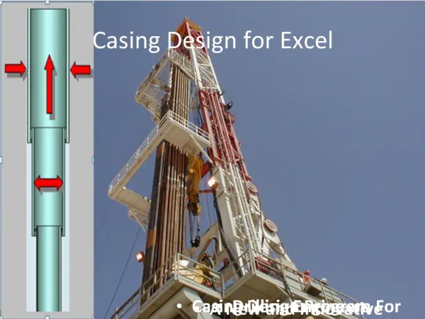
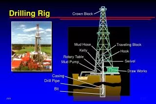
Dual Casing Running for deep water spud in. Presentation. Focusing the issue Deep water operation: Riserless top hole section Deep Water Dual Casing: MAIN PHASES OPTIONS REQUIRMENTS Applications Conclusions. Deep water activities: extreme environment

E N D
Presentation • Focusing the issue • Deep water operation: Riserless top hole section • Deep Water Dual Casing: MAIN PHASES • OPTIONS • REQUIRMENTS • Applications • Conclusions
Deep water activities: • extreme environment • heavy load conditions with unconsolidated sea bed • high daily spread rate The improvement of operations with the aim to increase the efficiency can produce a time reduction and as consequence a cost saving
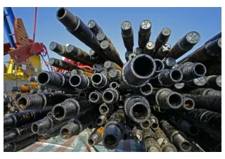
Conventional technique Jetting & Drill-Ahead • Drill 36” hole • Run and cement • 30” CP • Drill 26” hole • Run and cement • 20” csg • Jet 30” CP and • drill 26” hole • Run and cement • 20”csg
Traditional techniques – CONSTRAINS: • uncertainty about the formation to cross • perfect verticality of WH and correct stick up • not granted Deep Water Dual Casing
Conventional technique Jetting & Drill-Ahead Deep Water Dual Casing • Drill 36” hole • Run and cement • 30” CP • Drill 26” hole • Run and cement • 20” csg • Jet 30” CP and • drill 26”or 23” • Run and cement • 20”csg • Drill 23” x 36” hole with HO in tandem • Run and cement 30” CP and 20” csg • 1 jetting phase • 1 drilling phase • 1 cementing job • 2 round trips • 1 drilling phase • 1 cementing job • 2 round trips • 2 drilling phases • 2 cementing jobs • 4 round trips
Drill 23” or 17 1/2” hole No Rotation by using straight hole drilling device and motor
Drill 23” or 17 1/2” hole Start Rotation for 42” or 36” Hole
Drill 23”or 17 1/2” hole + 42” or 36” hole With Rotation for 36”/42” Hole The hole inclination approximately 0° (zero degree)
End of 23” or 17-1/2” hole + 42” or 36” hole POOH
36” or 42” hole + 23” or 17 1/2” hole
Ready to Run: Combination 36” or 30” C.P. + 20” csg or 20”+13 3/8” Tapered csg
MS 700 Wellhead SystemsGuidelineless Type Drilling System without Guide structure Cement Port Low-pressure Housing Lowered into Mud Mat Hydrate Gas Seals Shown with mud mat & ball valve
CART 18” 3/4 DA COMPLETARE Housing 18” 3/4 Housing 30” • Standard cement • DeepCRETE • Foam cement Mud Mat Casing 20” Conductor pipe 30” 36” Hole Casing 13 3/8” Inner string DP 5” 17 1/2” Hole
Case History ENI Angola 1 Job: 30”x20”x13 3/8” Casing 2 Jobs: 30”x20” Casing
ANGOLA OFFSHORE – CASE HISTORY # 1: Standard cement WD: 1300 m; Sea-bed temperature: 4 °C Shallow water risk: no Cement job: 30” C.P.x 20” x 13 3/8” tapered combined string Lead slurry: 1.44sg (12ppg) LiteFIL Tail slurry: 1.90sg (15.9ppg) Displacement: no cement returns at seabed WOC: 13 hrs Slack-off: casing string unstable WOC: additional 6 hrs Slack-off: OK Top job: cement job performed to ensure cement to sea bed
ANGOLA OFFSHORE – CASE HISTORY # 2: DeepCRETE Cement WD: 500 m; Sea-bed temperature: 6 °C Shallow water risk: yes Cement job: 30” C.P. x 20” casing Lead slurry: 1.20sg (10ppg) DeepCRETE with D500 GASBLOK Tail slurry: 1.90sg (15.9ppg) with D500 GASBLOK Displacement: returns at seabed WOC: 15 hrs Slack-off: casing string 1 cm “sink” WOC: additional 3 hrs Slack-off: OK Top job: no top job performed
ANGOLA OFFSHORE – CASE HISTORY # 3: Foam Cement WD: 1070 m; Sea-bed temperature: 5 °C Shallow water risk: no Cement job: 30” C.P. x 20” casing Lead slurry: 1.25sg (10.4ppg) Foam cement Tail slurry: 1.90sg (15.9ppg) Displacement: partial returns at seabed WOC: 15 hrs Slack-off: OK Top job: no top job performed
CART 18” 3/4 Housing 18” 3/4 Housing 30” Mud Mat Casing 20” 36” Hole Conductor pipe 30” Casing 13 3/8” Inner string DP 5” 17 1/2” Hole Wellhead cut and retrieved Annulus 20” - 30”
3 different options: • M/U C.P. and surf. csg during flat time and hang up them on Moon Pool trolley • M/U C.P. during flat time but surface casing on line after drilling tapered hole • M/U C.P. and surf. csg on line after drilling tapered hole
Requirements for full application: • VDL to load spud in materials • Motion compensator capability • Moon pool trolley capacity > (C.P.+surface csg+inner string) weight w/S.F. • Distance moon pool – sea bed > lenght of surface casing
If all requirements are NOT fully satisfied: • Partial time saving but all other advantages are exploited: • no C.P. sinking can occur • housing pre-fixed stick up and verticality near to 0° is granted • applicability in all lithology types • latch between LP and HPWH Housing performed at surface, ensuring mechanical structural integrity
Drill 8 ½” P.H. • M/U 36” C.P. • Run BOP • Drill 23”x42” hole • Run BOP • Run Dual csg string • Run BOP • Cementing op.
Operating time during riserless phase (drilling pilot hole and running BOP not included)
Deep water Dual Casing, a patented technology, is the most efficiency alternative to conventional techniques. • Advantages: • Hole inclination approximately 0 deg • Reduction of risk assessment in C.P. setting for unknown lithology • No subsidence events • Top Cement Job feasibility • LP HSG and HP HSG latch performed at surface • Time reduction • Constrain: • Water depth longer than surface casing setting depth (Reduction of system efficiency) • Rig technical characteristics • If shallow hazard phenomena imposes the use of 26” intermediate casing (36” LP HSG & CP)