Download
1 / 20
230 likes | 559 Views
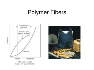
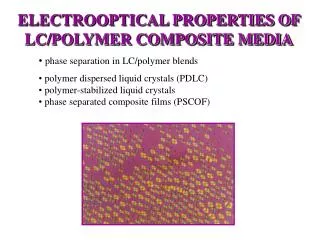
ELECTROOPTICAL PROPERTIES OF LC/POLYMER COMPOSITE MEDIA. phase separation in LC/polymer blends polymer dispersed liquid crystals (PDLC) polymer-stabilized liquid crystals phase separated composite films (PSCOF). Phase separation in liquid crystal/polymer blends.

E N D
ELECTROOPTICAL PROPERTIES OF LC/POLYMER COMPOSITE MEDIA • phase separation in LC/polymer blends • polymer dispersed liquid crystals (PDLC) • polymer-stabilized liquid crystals • phase separated composite films (PSCOF)
Phase separation in liquid crystal/polymer blends Formation of polymer matrix is the most important aspect of the composite devices. In most cases it bases on the polymerization induced phase separation process. The free energy of mixing for a polymer/LC system is described by two terms: 1) Flory-HugginsFE of liquid/liquid (de)mixing UCST • For > 2 two minima appear in Fmix(A), • which means that demixing takes place. • Demixing can be initiated by: • reducing the temperature of the mixture (TIPS) • increasing the unfavorable interaction energy between the costituents AB . • (for instance by initiating the polymerization process (PIPS) or by solvent evaporation (SIPS)). metastable
EFFECT OF ORIENTATIONAL ORDERING 2) Maier-Saupe FE describing orientational order of the LC constituents. angular distribution function nematic order paramer SN = <((3cos2)-1)/2> For(u/kT)>4.5 a minimum of FI-N(S) appears at S > 0, which means that transition to orientationally ordered (nematic) phase takes place.
POLYMER/LC DEMIXING Volume fraction of LC Decrease of entropy due to the alignment of LC molecules • Different combinations • of coexisting phases are possible: • I-I liquid-liquid isotropic phases • I-I-N two isotropic liquids + nematic • I-N isotropic liquid + nematic Cloud point T versus for different curing times (W52LC/polyester resin mixtures, curing t1<t2<t3) Phase diagram for uncured NOA65/E7 mixtures M. Mucha, Prog. Polym. Sci. 28, 837 (2003).
POLYMER/LC SOLUBILITY - Phase separation during polymer solidification is usually not complete, but some LC remains dissolved in the polymer matrix decreasing the polymer Tg. - On the other hand also some polymer constituents remain dissolved in the LC domains, which typically decreases the nematic-isotropic transition temperature TNI. The amount of demixed LC can be determined by calorimetric methods, IR spectroscopy.... mLC(PS) = mass of phase separated LC mLC = total mass of LC in the blend x = LC concentration (wt%) in the blend P(x) is determined from calorimetric (enthalpy) measurements. (W52LC mixed with 2 different polymers) Usually linear dependence of P(x) is found by experiments. M. Mucha, Prog. Polym. Sci. 28, 837 (2003).
POLYMER/LC MORPHOLOGY The final polymer/LC morphology is determined by domain size coarsening process, which is at some point hindered by diffusion restrictions related to the polymer matrix. Dynamical scaling law for domain size growth: R(t)(t)1/3 (Lifshitz-Slyozov law) Two nondestructive ways to study the morphology are optical microscopy, IR imaging, Photomicrographs showing growth of LC domains during TIPS (Photo by S. R. Challa, CWRU) Infrared (IR) spectroscopy provides information on the relative concentration of various species in a sample and their spatial distribution (http://plc.cwru.edu/tutorial/enhanced/files/pdlc/prep/prep.htm)
COMPOSITES WITH CROSS-LINKED POLYMER In case of cross-linked network formation, also the elastic free energy of the polymer network (network elasticity) contributes to the mixing/unmixing properties of the system. Entropy of mixing for cross-linked network = 0 y ay ay Elastic free energy of cross linked network (entropic!!) n = average number of polymer units extending between the two crosslinking points. ax x ax (a) (b) Comparison of theoretical phase diagrams for (a) NLC/linear polymer and (b) NLC/cross-linked polymer sytem. D. Nwabunma and T. Kyu, Macromolecules 32, 664 (1999)
EXAMPLE: K21/NOA65 system Optical polarization microscopy P 90% LC, 10% photo cross-linked polymer A D. Nwabunma and T. Kyu, Macromolecules 32, 664 (1999) LC/P composite structures are clasified on the basis of the morphological properties.
Polymer dispersed liquid crystals (PDLC) These are composite structures typically formed from mixtures with p>LC. They consist of spatially separated LC droplets embedded in a polymer matrix. + U - Side view of a PDLC cell Discovered in 1985 by J.W. Doane Kent, USA Typical droplet size ~ 1 m. The size and the shape of the droplets strongly depend on material composition and various parameters determining the phase separation process (phase composition of the initial state, curing temperature, curing rate, presence of external stress, EM fields, ...)
STRUCTURE OF NEMATIC DIRECTOR FIELD • LC orientational structure in the „cavity“depends on: • Anchoring properties at the LC/polymer interface • Size and shape of the cavity • Elastic constants of the LC • Temperature (with respect to the TNI) • Presence of external fields ^ n(r) = nematic director field = ? F=Fel+Fsurf+Ffield=min Boojum-type singularity Equatorial disclination line Bipolar structure Planar (tangential) strong anchoring Central defect Radial structure Homeotropic strong anchoring Axial structure Homeotropic weak anchoring R. Ondris-Crawford et al., J. Appl. Phys. 69, 6381 (1991) optical polarization microscopy
LIGHT SCATTERING FROM PDLC Practically all PDLC applications base on electric-field induced modification of light scattering properties (switchable windows, display devices, shutters...) • Light scattering from PDLC depends on: • Mismatch between the refractive index of the polymer and the LC (scattering intensity) • Size and shape of the LC domains (Rayleigh, Rayleigh-Gans, Mie scattering,...) • Configuration of nematic director field within the domains (Intradroplet interference) • Density of the LC domains (Interdroplet interference effects, multiple scattering...) , kr>>1 scattered radiation in the far field Example: radial structure Differential cross section Rayleigh-Gans approximation k‘ LC k dV r‘ p Scattering from a single droplet S. Zumer and J. W. Doane, Phys. Rev. A 34, 3373 (1986)
SwitchLite Privacy Glass™ EXAMPLE of SWITCHABLE STRUCTURE PDLC with bipolar droplets (http://plc.cwru.edu/tutorial/enhanced/files/pdlc/prep/prep.htm) (a) No Electric Field Random orientation of bipolar axes Strong scattering (b) Applied External Electric Field Aligned configuration of bipolar axes Low scattering (especially if np = no,LC) Transmittance (%) Typical transmittance versus voltage dependence E202/NOA 65 composite R. Karapinar, 1998 Voltage (V)
SWITCHING FIELD and SWITCHING TIME The switching process is governed by competition between: a) elastic torque, b) field torque, c) viscous torque and by boundary conditions at the LC/polymer interface • Basic parameters, which affect the switching properties of a single LC droplet: • dielectric anisotropy of the LC (10) • surface anchoring of at the LC-polymer interface (Ws10-6-10-4 Jm-2)boundary conditions!! • size and shape of the LC domain (ellipsoid:a,b500 nm, axial ratio I=(a/b)1-3) • orientation of the LC within the domain (structure of n(r)) • viscoelastic constants of the LC (K10 pN, 0.01 kgm-1s-1) Specific example: ellipsoidal droplet with axial configuration and n0E : Threshold field ~ 1 V/m 0 E Switching-on time (E>>Ec) 0 b Switching-off time ~ 1 ms a B. G. Wu at al., Liquid Crystals 5, 1453 (1989)
REAL SWITCHING DYNAMICS 100 Hz/8 V switching voltage Tranmittance of 2 m thick PDLC cell R. Karapinar, 1998 In reality the relaxation (switching-off) process takes place over several decades and exhibits complex (glass-like) dynamic features. (reasons: shape anomaly, interface roughness, interconnected domains, motion of ionic impurities, coupling between LC and elastic network,...) I. Drevenšek-Olenik et al., to appear in J. Appl. Phys. (2006).
Polymer-stabilized liquid crystals (known also as: polymer network LCs, polymer-filled LCs, LC gels) These are composite structures typically formed from mixtures with LC>>p. They consist of polymer voids forming a 3D network within the continuous LC phase. SEM image of a typical PDLC 60 wt% polymer, 40 wt% LC M. Čopič and A. Mertelj, Phys. Rev. Lett. 80, 1449 (1998) SEM image of a typical polymer-filled LC 20 wt% polymer, 80 wt% LC M. Mucha, Prog. Polym. Sci. 28, 837 (2003). Polymer network provides mechanical stability of the LC structure !!
SWITCHABLE WINDOWS from PSLC Competition between surface constraints at substrates, polymer network/LC interface interaction and field induced torque. (b) (a) Two types of PSLC Structures: Polymer fibrils (a) and polymer walls (b). LC acrylates + non-reactive LC Transmittance (%) Transmittance (%) RMS Voltage (V) RMS Voltage (V) T(U) for 5 (squares), 7 (circles), and 10 (crosses) volume % fraction of the polymer, d = 6 m. R. A. M. Hikmet and H. M. J. Boots, Phys. Rev. E 51, 5824 (1995).
SOME OTHER APPLICATIONS Electrically switchable mirrors, Fresnel lenses, ... Voltage On Voltage Off Broad-band selective reflection from polymer stabilised cholesteric structure (=p(ne-no)) In usual cholesteric LC cells surface alignment layers are unable to restore the homogeneous helical configuration after the switching, so polymer network is used to increase the restoring force (in-situ photopolymerization = patterned gels). Transmittance (%) wavelength (nm) UV curable LC acrylates + non-reactive LC Selective reflection at different applied voltages. R. A. M. Hikmet and H. Kemperman, Nature 329, 1998
Phase separated composite films (PSCOF) These is a very thin layer of phase separated LCin contact with a polymer layer. They are obtain by photopolymerization using optical wavelengths in the region of absorption band of the liquid crystal, which produces intensity gradient along the z axis. I(z) Polymer + U + U - Liquid crystal - Rubbed PI layer Photopolymerization takes place in the region of higher UV intensity. LC is accu-mulated in the region of low UV intensity. Cell filled with mixture of LC/polymer precursor (T>>TNI). z For instance NOA 65 + E7 (60/40) The rate of phase separation is most important factor determining the final structure! Q. Wang et al., 2004
EXAMPLE OF A DEVICE based on PSCOF Microlens with E-switchable focus Q. Wang, at al., 2004 (group of S. Kumar) m f=1cm, 2R~200 These kinds of lens-arrays can be addressed similar way as LCDs (promising for applications in robotics...) General advantages of PSCOF: Easy and precise control of LC thickness (sub ms response time with sub micrometer films), mechanical ruggedness, flexibility, plastic substrates can be used, only one alignment layer is needed (convenient for TFT technoogy)...
SOME OTHER COMPOSITE STRUCTURES • LCs in colloid templated polymer cavities • Liquid crystal/polymer membranes • Liquid crystal/polymer/azobenzene composites • Surface relief gratings with LCs • Liquid crystal/liquid crystal polymer blends • ... Texture of LC/polymer mixture The number of different LC/P composite architectures is limited only by imagination!!