Polymer and Ceramic Processing
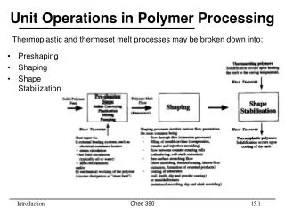
Polymer and Ceramic Processing. Outline . Polymer Processing Techniques Polymer Additives Ceramic Fabrication Methods Glass Forming Particulate Forming Cementation. Forming Processes for Polymers . Compression Molding Injection Molding Extrusion Blow Molding. Processing Details.

Polymer and Ceramic Processing
E N D
Presentation Transcript
Outline • Polymer Processing Techniques • Polymer Additives • Ceramic Fabrication Methods • Glass Forming • Particulate Forming • Cementation
Forming Processes for Polymers • Compression Molding • Injection Molding • Extrusion • Blow Molding
Processing Details • Blow Molding Techniques • Extrusion [hose and tubing, belts, rope and cable covers, sheeting and films] • Foaming Techniques Foam molding offers the possibility of increasing the size of a part without increasing weight and reducing the weight of a part with controlled change of properties. Chemical foaming involves mixing a chemical blowing agent with pellets prior to the pellets being fed into the feed throat of the molding machine. • Injection Molding Most engineering thermoplastic parts are fabricated by injection molding. http://www2.dupont.com/Plastics/en_US/Knowledge_Center/Processing/processing_methods.html
Polymer Formation • Thermoplastic - can be reversibly cooled & reheated, recycled; heat until soft, shape, then cool. • examples: polyethylene, polypropylene, polystyrene. • Thermoset - when heated, forms a molecular network (chemical reaction), degrades (doesn’t melt) when heated. • examples: urethane, epoxy 5
Additives for Plastics • Fillers • Pigments • Stabilizers • Antistatic Agents • Flame Retardants • Plasticizers • Reinforcements • Catalysts
Improve mechanical properties, processing, durability. Fillers - Added to improve tensile strength & abrasion resistance, toughness & decrease cost. Examples: carbon black, silica gel, wood flour, glass, limestone, talc. Plasticizers - Added to reduce the glass transition temperature Tg below room temperature. Presence of plasticizer transforms brittle polymer to a ductile one. Commonly added to PVC. Stabilizers – Antioxidants, UV protection Lubricants - Added to allow easier processing polymer “slides” through dies easier (sodium stearate). Colorants - Dyes and pigments Flame Retardants - Substances containing chlorine, fluorine and boron. Polymer Additives
More Additives • Antimicrobials: Used to control the build up of bacteria, fungi and algae on the surface of plastic products. A wide range of chemical and natural compounds are used as antimicrobials. An example would be naturally occurring silver ions used in products like cell phones or organic acids in food-related products. • Antistatics:Used to minimize static electricity. These types of additives can be mixed with the resin or applied to the surface of the product. Antistatic additives are common to a wide variety of products ranging from cosmetics to industrial goods to sensitive electronic parts. • Fibers:Used to increase strength and stiffness. The most common type of fibers added for strength would be carbon and glass. Glass-reinforced plastic is more commonly known as fiberglass.
Processing Plastics – Compression Molding Thermoplastics and thermosets polymer and additives placed in mold cavity mold heated and pressure applied fluid polymer assumes shape of mold 9 9
Processing Plastics – Injection Molding • Thermoplastics and some thermosets • when ram retracts, plastic pellets drop from hopper into barrel • ram forces plastic into the heating chamber (around the spreader) where the plastic melts as it moves forward • molten plastic is forced under pressure (injected) into the mold (die) cavity where it assumes the shape of the mold Barrel http://en.wikipedia.org/wiki/Injection_mold 10 10
Plastic Injection Molding • Operate 30 plastic injection molding machines from 22 tons to 550 Tons and 60 oz. shot capacity. Many machines are capable of multiple core pulls for complex plastic injection molded parts. • Plastic injection molding group services mid-sized manufacturing companies in the energy, electronics, life science, aerospace, food and beverage, industrial and construction markets. As a custom plastic injection molder we seek diversity in many markets and focus our skills on part geometry for molding, material and product application. • Our plastic injection molding group processes most commodity and engineering injection molded resins including PS, PE, PP, ABS, SAN, PC, PVC, PBT, PPS, TPO, TPU, POM, Nylon 66, Nylon 11 and many custom compounded engineering resins. http://www.blackwellplastics.com/PlasticRodExtrusion.html
Processing Plastics – Extrusion • Thermoplastics • plastic pellets drop from hopper onto the turning screw • plastic pellets melt as the turning screw pushes them forward by the heaters • molten polymer is forced under pressure through the shaping die to form the final product (extrudate) 12 12
Extrusion of Plastics In the extrusion of plastics, raw thermoplastic material in the form of small beads (resin) is gravity fed from a top mounted hopper into the barrel of the extruder. Additives (colorants and UV inhibitors in either liquid or pellet form) are often used and can be mixed into the resin prior to arriving at the hopper. The material enters through the feed throat (an opening near the rear of the barrel) and comes into contact with the screw. The rotating screw (normally turning at up to 120 rpm) forces the plastic beads forward into the barrel which is heated to the desired melt temperature of the molten plastic (which can range from 200°C/400°F to 275°C/530°F depending on the polymer). In most processes, a heating profile is set for the barrel where three or more independent PID controlled heater zones gradually increase the temperature of the barrel from the rear (where the plastic enters) to the front. This allows the plastic beads to melt gradually as they are pushed through the barrel and lowers the risk of overheating which may cause degradation in the polymer. 13
Processing Plastics – Blown-Film Extrusion • The manufacture of plastic film for products like shopping bags is done using a blown film line. • This process is the same as a regular extrusion process up until the die. The die is an upright cylinder with a circular opening similar to a pipe die. The diameter can be a few cm to more than 3 m across. The molten plastic is pulled upward from the die by a pair of rollers high above the die. • Changing the speed of these rollers changes the gauge (wall thickness) of the film. Around the die sits an air-ring. The air-ring cools the film as it travels upward. In the center of the die is an air outlet where compressed air can be forced into the center of the extruded circular profile, creating a bubble. 14 14
c14f15 Ceramic Fabrication Methods
Glass A glass is an inorganic non metallic material that does not have a crystalline structure. Such materials are said to be amorphous and are virtually solid liquids cooled at such a rate that crystals have not been able to form. Typical glasses range from the soda-lime silicate glass for soda bottles to the extremely high purity silica glass for optical fibers. Glass is widely used for windows, bottles, glasses for drinking, transfer piping and receptacles for highly corrosive liquids, optical glasses, windows for nuclear applications. Most products have been blown glass. In recent times, most flat glass has been produced using the float process. Mass produced bottles and decorative products are made using industrial scale blown glassprocess.
Glass Properties: Viscosity t dy dv glass dv dy t velocity gradient • Viscosity, h ,describes a fluid's internal resistance to flow and may be thought of as a measure of fluid friction. -- relates shear stress () and velocity gradient (dv/dy): hhas units of (Pa-s) Glass or noncrystalline materials do not solidify in the same sense as crystalline materials. Upon cooling, a glass becomes more and more viscous with decreasing temperature. 17
c14f17 Important in glass forming operations are the viscosity-temperature characteristics of glass. Temperatures: Melting Point: viscosity = 10 Pa-s; glass is fluid enough to be considered liquid. Working Point: viscosity = 103 Pa-s; glass is easily deformed. Softening Point: viscosity = 4x10⁶ Pa-s; max temp. glass can be handled without altering dimensions. Annealing Point: viscosity = 1012 Pa-s; good atomic diffusion; stress relief. Strain Point: viscosity = 3 x 10¹³ Pa-s; below strain point, fracture will occur before the onset of plastic deformation .
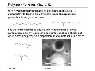
Glass Properties Liquid Supercooled (disordered) Liquid Glass (amorphous solid) Crystalline (ordered) r=density • Specific volume (1/r) vs Temperature (T): • Crystalline materials: -- crystallize at melting temp, Tm -- have abrupt change in specific volume at Tm Specific volume • Glasses: -- do not crystallize -- change in slope in spec. vol. curve at glass transition temperature, Tg -- transparent - no grain boundaries to scatter light solid T Tg Tm 19
Log Glass Viscosity vs. Temperature fused silica glass 96% silica soda-lime Pyrex 14 10 strain point annealing point 10 10 Viscosity [Pa-s] 6 Working range: glass-forming carried out 10 2 10 Tmelt 1 T(°C) 200 600 1000 1400 1800 • soda-lime glass: 70% SiO2 balance Na2O (soda) & CaO (lime) • Viscosity decreases with T • borosilicate (Pyrex): 13% B2O3, 3.5% Na2O, 2.5% Al2O3 • Vycor: 96% SiO2, 4% B2O3 • fused silica: > 99.5 wt% SiO2 20
c14f18 Glass Blowing • Some glass blowing is done by hand. • The process is completely automated for the production of glass jars, bottles and light bulbs. • From a raw gob of glass, a parison (temporary shape) is formed by mechanical pressing in a mold. • This piece is inserted into a finishing or blow mold and forced to conform to the mold contours by the pressure created from a blast of air. • Drawing is used to form long glass parts (sheets, rods, tubing and fibers) that have a constant cross section.
Sheet Glass Forming Sheet forming – continuous casting sheets are formed by floating the molten glass on a pool of molten tin 22
Heat Treating Glass before cooling initial cooling at room temp. compression cooler hot hot tension compression cooler -- Result: surface crack growth is suppressed. • Annealing: -- removes internal stresses caused by uneven cooling. • Tempering: -- puts surface of glass part into compression -- suppresses growth of cracks from surface scratches. -- sequence: 23
Tempered Glass Fully tempered glass is roughly 4 times stronger than annealed glass of the same thickness and configuration; residual surface compression must be over 10,000 psi for 6mm thickness, according to ASTM C 1048. Tempered glass is manufactured through a process of extreme heating and rapid cooling, making it harder than normal glass. The typical process to produce tempered glass involves heating the glass to over 1,000 °F, then rapidly cooling to lock the glass surfaces in a state of compression and the core in a state of tension. When glass cools down to ambient temperature, the center plane of the glass contracts more than the surfaces. The contraction of the center plane pulls the surfaces into compression and the glass becomes very strong. Tempered glass cannot be cut or drilled after tempering, and any alterations, such as edge-grinding, sandblasting or acid-etching, can cause premature failure.
Tempering Process Fabrication occurs on electrically heated horizontal furnaces that heat the glass to a uniform temperature of roughly 1200°F. Ceramic rolls convey the glass through these furnaces at speeds regulated to ensure temperature uniformity and minimal optical distortions. When the glass exits from the furnace, it is rapidly cooled by a series or air nozzles. This rapid cooling puts roughly 20% of the glass surface into a state of compression, with the center core in tension.
Shattered Tempered Glass The brittle nature of tempered glass causes it to shatter into small oval-shaped pebbles when broken. This eliminates the danger of sharp edges. Due to this property, along with its strength, tempered glass is often referred to as safety glass. Tempered glass breaks in a unique way. If any part of the glass fails, the entire panel shatters at once. This distinguishes it from normal glass, which might experience a small crack or localized breakage from an isolated impact. Tempered glass might also fail long after the event that caused the failure. Stresses continue to play until the defect erupts, triggering breakage of the entire panel.
Heat-strengthened (Hs) glass has been heated and cooled and is generally twice as strong as annealed glass of the same thickness and configuration. Hs glass has greater resistance to thermal loads than annealed glass and, when broken, the fragments are typically larger than those of fully tempered glass. It does not require the strength of fully tempered glass, and is intended for applications that do not specifically require a safety glass product. Heat Strengthened Glass • Hs glass must achieve residual surface compression between 3,500 and 7,500 psi for 6 mm glass, according to ASTM C 1048. • Hs glass cannot be cut or drilled after heat-strengthening and any alterations, such as edge-grinding, sandblasting or acid etching can cause premature failure.
Annealed Glass Annealing float glass is the process of controlled cooling to prevent residual stress in the glass. It is part of the float glass manufacturing process. Annealed glass can be cut, machined, drilled, edged and polished. To anneal glass, the glass is heated and kept for a defined period of time to relieve internal stresses. Carefully cooled under controlled conditions to ensure that no stresses are reintroduced by chilling/cooling. • Float glass (also called “flat” glass) has not yet been heat-strengthened or tempered.
Glass Properties P - Pressed Ware R - Rolled Sheet S - Ground & Polished T - Tubing & Rod U - Panels 1100 KHz 225-1000°C 320-1000°C B - Blown Ware C - Cast D - Drawn Sheet E - Extruded F - Frit & Powdered Glass G - Gob & Strip K - Special Cane M - Multiform
Different techniques for processing advanced ceramics. The space shuttle makes use of ~25,000 reusable, lightweight, highly porous ceramic tiles that protect the aluminum frame from the heat generated during re-entry into the Earth’s atmosphere.
Typical steps encountered in the processing of ceramics. Green ceramic - A ceramic that has been shaped into a specific form but has not yet been sintered.
Mechanical Properties of Advanced Ceramics Typical Porcelain Composition (50%) 1. Clay (25%) 2. Filler – e.g. quartz (finely ground) (25%) 3. Fluxing agent (Feldspar) -- aluminosilicates plus K+, Na+, Ca+ -- upon firing - forms low-melting-temp. glass
CEREC Technology • An optical 3D image is acquired with a small camera, directly in your mouth. • The computer and CEREC® 3D software converts the digital picture to a three dimensional virtual model of your prepped tooth. Your dentist then designs your restoration right on screen using the software. • This software can handle single tooth restoration: crowns, inlays (fillings), onlays (partial crowns), and veneers. After the design is complete, the data is transmitted via a wireless radio signal to the CEREC® Milling Unit. • Diamond coated instruments mill a ceramic block to reproduce the design. • This is done during a single appointment using Computer Aided Design/Computer Aided Manufacture (CAD/CAM). http://www.sirona.com/ecomaXL/index.php?site=SIRONA_COM_cadcam_systems
Ceramic Materials • When creating CEREC restorations, you can choose from feldspar ceramics, glass ceramics and high-performance polymers. • They are biocompatible, clinically tested, durable and metal-free. Problems due to corrosion and incompatibility can be virtually ruled out. • The ceramic materials fulfill stringent standards in terms of fracture toughness, abrasion, aesthetics and machinability. Sirona has developed its own range of machinable ceramic blocks for the CEREC and inLab CAD/CAM systems. • Sirona inCoris materials consists of partially sintered framework ceramics – they provides the basis for manufacturing high-precision all-ceramic crowns and bridge restorations made of aluminium and zirconium oxide.
Slip Casting drain pour slip pour slip “green absorb water mold into mold into mold into mold ceramic” “green ceramic” hollow component A liquid clay body (a slip) is poured into a plaster mold and allowed to form a layer on the inside cavity of the mold. In a solid cast mold, ceramic objects like handles and platters are surrounded by plaster on all sides with a reservoir for slip, and are removed when the solid piece is held within. For a hollow cast mold, once the plaster has absorbed most of the liquid from the outside layer of clay the remaining slip is poured off for later use. The cast piece is removed from the mold, trimmed and dried. This produces a green piece that is then fired, with or without decoration and glaze. The technique is suited to the production of complex shapes, and is commonly used for toilets, basins, figurines and teapots. The technique can also be used for small scale production runs. 35 solid component
Hydroplastic Forming A o container die holder force ram A billet extrusion d die container • Hydroplastic forming - Processes where a moist ceramic clay body is formed into a useful shape. • Mill (grind) and screen constituents: desired particle size. • Extrude the mass. • Dry and fire the formed piece. 36
Drying and Firing wet body partially dry completely dry Si02 particle • Firing: -- heat treatment between 900-1400°C -- vitrification: liquid glass forms from clay and flux – flows between SiO2 particles. (Flux lowers melting temperature). (quartz) glass formed micrograph of porcelain around the particle 70mm • Drying: as water is removed - interparticle spacings decrease – shrinkage. Drying too fast causes sample to warp or crack due to non-uniform shrinkage 37
Shear charge neutral weak van der Waals bonding 4+ charge Si 3 + neutral Al - OH 2- O Shear Kaolinite • Clay is inexpensive. • Kaolinite is a clay mineral with the chemical composition Al2Si2O5(OH)4. • It is a layered silicate mineral, with one tetrahedral sheet linked through oxygen atoms to one octahedral sheet of alumina octahedra. • When water is added to clay, water molecules fit between layered sheets, reducing degree of van der Waals bonding; (Can shear along vdW bonds more easily). • When external forces are applied, clay particles are free to move past one another, becoming hydroplastic. • Adding water to clay enables extrusion and slip casting. • Kaopectate, paper, pipes (smoking). Structure of Kaolinite Clay
Powder Pressing • Used for clay and non-clay compositions. • Powder (plus binder) compacted by pressure in a mold. Microstructure of a barium magnesium tantalate (BMT) ceramic prepared using compaction and sintering. (Courtesy Heather Shivey.) • Uniaxial compression - compacted in single direction • Isostatic (hydrostatic) compression - pressure applied by fluid - powder in rubber envelope • Hot pressing - pressure + heat. 40
Sintering 15m • Sintering occurs during firing of a piece that has been powder pressed, powder particles coalesce and pore size is reduced. • Typically, ceramics with a small grain size are stronger than coarse-grained ceramics. • Finer grain sizes help reduce stresses that develop at grain boundaries due to anisotropic expansion and contraction. Aluminum oxide powder: -- sintered at 1700°C for 6 minutes. 41
c14f28 Tape Casting Tape casting - A process for making thin sheets of ceramics using a ceramic slurry consisting of binders, plasticizers, etc. The slurry is cast as tape with the help of a blade onto a plastic substrate. Used for integrated circuits and capacitors Slip = suspended ceramic particles + organic liquid
Ceramic Fabrication Methods - Cementation • Hardening of a paste: paste formed by mixing cement material with water. • Formation of rigid structures having varied and complex shapes. • Hardening process: hydration (complex chemical reactions involving water and cement particles). • Production of Portland cement: • mix clay and lime-bearing minerals • calcine (heat to 1400°C) • grind into fine powder 43