Download

1 / 52
1.26k likes | 2.21k Views
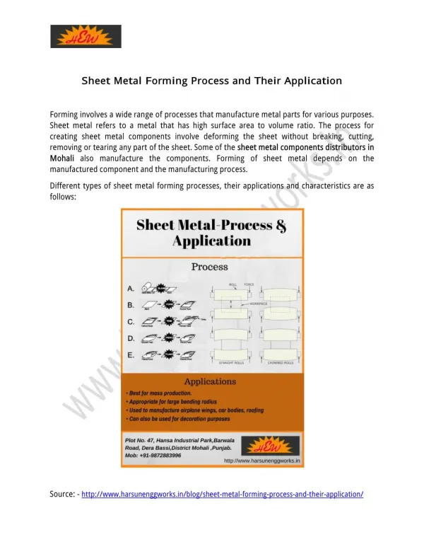
SHEET METAL FORMING. INTRODUCTION. Formability may be defined as the ease with which material may be forced into a permanent change of shape.

E N D
INTRODUCTION • Formability may be defined as the ease with which material may be forced into a permanent change of shape. • The formability of a material depends on several factors. The important one concerns the properties of material like yield strength, strain hardening rate, and ductility. • These are greatly temperature – dependent.
As the temperature of material is increased, the yield strength and rate of strain hardening progressively reduce and ductility increases. • The hot working of metal, therefore, permits relatively very large amount of deformation before cracking.
There are several methods of predicting formability. A brief description of some important methods follows :
Cup or Radial Drawing • Cup drawing test uses a circular blank from the metal to be tested. • It is inserted in a die, and the severity of the draw it is able to withstand without tearing called the drawing ratio, is noted. • The drawing ratio is the ratio of the cup diameter to the blank diameter.
Where Rd = drawing ratio D = blank diameter d = punch diameter
A drawing ratio of 50 % is considered excellent. • As shown in Fig 4.1(a), either a flat bottom punch with lubricated blank may be used to draw the cup, or as shown in Fig 4.1(b) a blank may be drawn by a lubricated hemi spherical punch.
In the first case, the action is principally that of drawing in which cylindrical stretching of material takes place. • In the second case, there will be bi axial stretching of the material. • For drawing, the clamping force is just sufficient to prevent buckling of the material at the draw radius as it enters the die. • The deformation takes place in the flange and over the draw radius.
SHEARING • Shearing is a cutting operation used to remove a blank of required dimensions from a large sheet. • To understand the shearing mechanism, consider a metal being sheared between a punch and a die, Fig 5.1 . • Typical features of the sheet and the slug are also shown in this figure. • As can be seen that cut edges are neither smooth nor perpendicular to the plane of the sheet.
Shearingstartsas the punch presses against the sheet metal. • At first, cracks form in the sheet on both the top and bottom edges (marked T and T', in the figure). • As the punch descends further, these cracks grow and eventually meet each other and the slug separates from the sheet.
A close look at the fractured surfaces will reveal that these are quite rough and shiny; • Rough because of the cracks formed earlier • Shiny because of the contact and rubbing of the sheared edge against the walls of the die.
The clearance between the punch and the die plays an important role in the determination of the shape and quality of the sheared edge. • There is an optimum range for the clearance, which is 2 to 10% of the sheet thickness, (t) for the best results.
If the clearance increases beyond this, the material tends to be pulled into the die and the edges of the sheared zone become rougher. • The ratio of the shining (burnished) area to the rough area on the sheared edge decreases with increasing clearance and sheet thickness. • The quality of sheared edge is also affected by punch speed; greater the punch speed better the edge quality.
Shearing Operations • For general purpose shearing work, straight line shears are used. as shown in Fig , small pieces (A, B, C, D) may be cut from a large sheet.
Shearing may also be done between a punch and die, as shown in Fig. • The shearing operations make which use of a die, includepunching, blanking, piercing, notching, trimming, and nibbling.
Punching/Blanking • Punching or blanking is a process in which the punch removes a portion of material from the largerpiece or a strip of sheet metal. • If the small removed piece is discarded, the operation is called punching. • whereas if the small removed piece is the useful part and the rest is scrap, the operation is called blanking, see Fig 5.3.
Comparison of basic stamping operations. In punching, the metal inside the part is removed; in blanking, the metal around the part is removed.
A typical setup used for blanking is shown in Fig Fig 5.4 Blanking punch and die.
The clearance between the die and punch can be determined as c = 0.003 t, where t is the sheet thickness and τ is the shear strength of sheet material. • For blanking operation, die size = blank size, and the punch is made smaller, by considering the clearance. • The maximum force, P required to be exerted by the punch to shear out a blank from the sheet can be estimated as • P = t. L. τ
Stripping force. Two actions take place in the punching process , punching and stripping. • Stripping means extracting the punch. • A stripping force develops due to the spring back (or resiliency) of the punched material that grips the punch. • This force is generally expressed as a percentage of the force required to punch the hole, although it varies with the type of material being punched and the amount of clearance between the cutting edges.
The following simple empirical relation can be used to find this force • SF = 0.02 L.t • where SF = stripping force, kN • L = length of cut, mm • t = thickness of material, mm
Example: A circular blank of 30 mm diameter is to be cut from 2 mm thick 0.1 C steel sheet. Determine the die and punch sizes. Also estimate the punch force and the stripping force needed. You may assume the following for the steel : Tensile strength: 410 MPa ; shear strength : 310 MPa
Solution:- For cutting a blank, die size = blank size \ Die size = 30mm • Clearance = 0.003 x t x τ = 0.003 x 2 x 310 = 1.86 mm • Punch size = blank size - 2 clearance = 30 - 2 x 1.86 = 26.28 mm
Punch force needed = L. t. τ = π x 30 x 2 x 310 • = 58.5 kN • Stripping force needed = 0.02 L.t • = 0.02 x π x 30 x 2 • = 3.77 N
Piercing: • It is a process by which a hole is cut (or torn) in metal. • It is different from punching in that piercing does not generate a slug. Instead, the metal is pushed back to form a jagged flange on the back side of the hole. • A pierced hole looks somewhat like a bullet hole in a sheet of metal.
Trimming: • When parts are produced by die casting or drop forging, a small amount of extra metal gets spread out at the parting plane. • This extra metal, called flash, is cut off before the part is used, by an operation called trimming. • The operation is very similar to blanking and the dies used are also similar to blanking dies. The presses used for trimming have, however, relatively larger.
Notching: • It is an operation in which a specified small amount of metal is cut from a blank. • It is different from punching in the sense that in notching cutting line of the slug formed must touch one edge of the blank or strip. • A notch can be made in any shape. The purpose of notching is generally to release metal for fitting up.
Nibbling: • Nibbling is variation of notching, with overlapping notches being cut into the metal. • The operation may be resorted to produce any desired shape, for example flanges, collars, etc.
Perforating: • Perforating is an operation is which a number of uniformly spaced holes are punched in a sheet of metal. • The holes may be of any size or shape. • They usually cover the entire sheet of metal.
BENDING • Bending is one very common sheet metal forming operation used not only to form shapes like seams, corrugations, and flanges but also to provide stiffness to the part (by increasing its moment of inertia).
Fig 6.1 Sheet metal bending. It may be noted that the bend radius is measured to the inner surface of the bent part.
As a sheet metal is bent (Fig 6.1), its fibres experience a distortion such that those nearer its outside, convex surface are forced to stretch and come in tension, while the inner fibres come in compression. Somewhere, in the cross section, there is a plane which separates the tension and compression zones
This plane is parallel to the surface around which the sheet is bending, and is called neutral axis. The position of neutral axis depends on the radius and angle of bend. Further, because of the Poisson's ratio, the width of the part L in the outer region is smaller, and in the inner region it is larger, than the initial original width
BEND ALLOWANCE • It is the length of the neutral axis in the bend, Fig 6.1. This determines the blank length needed for a bent part. It can be approximately estimated from the relation Lb = α ( R + kt ) where, Lb = bend allowance (mm) α = bend angle (radian) , R = bend radius (mm) t = thickness of sheet (mm), and k = constant, whose value may be taken as 1/3 when R < 2t, and as 1/2 when R > 2t.
Example : A 20 mm wide and 4 mm thick C 20 steel sheet is required to be bent at 600 at bend radius 10 mm. Determine the bend allowance. Solution. Here, bend radius, R = 10 mm Sheet thickness, t = 4 mm We know that,
Since R > 2t, k = 0.5 • Bend allowance , Lb
MINIMUM BEND RADIUS • As the ratio of the bend radius to the thickness of sheet (R / t) decreases, the tensile strain on the outer fibres of sheet increases. • If R / t decreases beyond a certain limit, cracks start appearing on the surface of material. This limit is called Minimum Bend Radius for the material. • Minimum bend radius is generally expressed in terms of the thickness of material, such as 2t, 3t, 4t, etc. Table 6.1 gives the minimum bend radius allowed for different materials.
Table 6.1 Minimum Bend radius for Various Materials at Room Temperature ;
Bending Force • There are two general types of die bending : a) V die bending b) wiping die bending. V die bending is used extensively in brake die operations and stamping die operations. The bending force can be estimated from the following simple relation P = k.Y.L.t2 / D
where P is bending force, • g is the yield stress of the material, • L is the bend length ( bend allowance ), • t is the sheet thickness, • D is the die opening and • k is a constant whose value can be taken as 1.3 for a V-die and 0.3 for a wiping die. Fig 6.2 shows various types of bending dies.
Bending force varies as the punch progresses through the bending operation. The force is zero in the beginning. It rises and reaches the maximum value as the punch progresses and reaches the bottom of the stroke.
Example: • A 400 mm long and 2.5 mm thick piece of carbon steel sheet is required to be bent at 900 using a V die. You may assume the yield stress of the material as 500 M Pa and the die opening as 10 times the material thickness. Estimate the force required for the operation.
Solution : • Here, Y = 500 M Pa • L = 400 mm • t = 2.5 mm • k = 1.3 (for V die) • D = 25 mm • Bending force P = k.Y.L.t2 / D • = 1.3 x 500 x 400 x (2.5)2 / 25 • = 65 KN