Download
1 / 1
10 likes | 135 Views
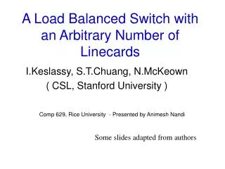
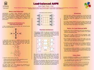
r. r. 0. 0. R. R. X. 1. X. 1. R. R. X. N-1. N-1. R. R. Crossbars (Core Node). Source Nodes. Destination Nodes. Load-balanced AAPN Sareh Taebi, Trevor J. Hall

E N D
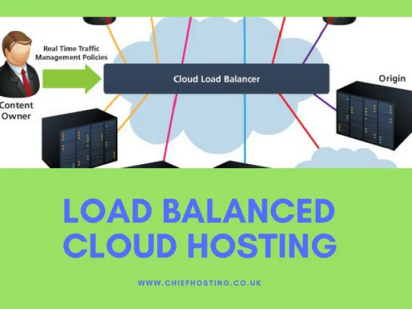
r r 0 0 R R X 1 X 1 R R X N-1 N-1 R R Crossbars (Core Node) Source Nodes Destination Nodes Load-balanced AAPN Sareh Taebi, Trevor J. Hall Photonic Network Technology Laboratory, Centre for Research in Photonics School of Information Technology and Engineering, University of Ottawa 800 King Edward Avenue, Ottawa ON K1N 6N5. { staebi, thall } @site.uottawa.ca What is load-balancing? Load-balancing in general means distributing, processing and communicating evenly across a device so that no single section is overwhelmed. Load balancing is especially important for networks where it is difficult to predict the number of requests that will be issued to a server. Load-balancing can therefore also be applied to the network switching devices to avoid congestion in any section of a switch/network. Architectural Derivation of a load-balanced switch 1. Take a Centralised Shared Memory Switch with cross-point queues Qij for every input-output pair i, j. Load balanced switch architecture: Scheduling Ideally the central crossbars are scheduled on a per-slot basis using queue state information, but the signaling delay would mean that the queue-state is out-of-date. A better option is to take a frame based approach and change the configuration of the central nodes every frame slot. If the load is perfectly balanced, then each crossbar would have the same schedule. Therefore one wavelength independent crossbar could be used in the core node to switch the wavelength multiplex as whole. This is called “Photonic Slot Routing” in the literature. • Merits of a Load-Balanced AAPN • Packets within a flow are transported to their correct destinations in sequence. This is due to the 1:1 logical connection of the buffers and use of load-balancing pollers. • Since a flow of traffic is spread across all wavelengths, 100% throughput is guaranteed even for very high loads and bursty traffic with a modest buffer requirement. • One wavelength independent cross-bar would suffice in the core node to switch the wavelength multiplex as whole, because the load is nearly equally balanced among wavelengths. • Complexity is reduced greatly since only one schedule is needed for all the wavelengths. This schedule may be calculated only once per-frame, as opposed to per-slot, reducing the scheduling complexity even further. • The load-balanced AAPN is survivable; i.e. in case of a failed layer, the packets will be distributed among the remaining layers. In this case, the pointers will skip over queues labeled by the failed layer and only serve the remaining queues. Resultant Architecture In the context of AAPN, the Layers can be identified each with a wavelength within a wavelength multiplex. The central crossbars then form the stacked crossbar switches within the core node of the AAPN network.The inputs and outputs of the switch correspond to the source and edge nodes. 2. Split further every queue as a LAYERED cross-point queue with load-balancing pollers. The pollers move round-robin to serve the layered queues in turn. Also, divide every queue into ‘heads’ and ‘tails’ labeled with 1 and 2 respectively. Q1ijkis the queue corresponding to input i, output j and layer k. Note that the transmit buffers are VOQs (one fore each destination edge node), the receive buffers are VIQs (one for each source edge node). The co-ordination buffers in the source edge node are per wavelength (i.e. layer). The resequencing buffers in the destination edge node are VIQs per wavelength (layer). The flows to each destination edge node are spread evenly over wavelength by per-destination edge node pollers in the source edge node. The flows are reconstructed by per-source pollers in the destination edge node. The pollers work independently, but serve packets in the same order to preserve synchronization. • Future Work • Currently investigating the possibility of a more sophisticated flow dependent slot aggregation algorithm between the extremes of: • (i) no load balancing and a per-layer scheduler, as performed by other bandwidth allocation algorithms; and • (ii) load-balancing with an all-layer scheduler, as presented here • Packet loss in the switch will cause pollers to run out of sequence and therefore packets will arrive out of sequence. A simple and effective solution to this problem is being investigated. • 3. Sector the shared memory switch and: • Place the queue tails in the input stage organized as a set of Virtual Output Queues (VOQ) for each input. • Place the heads in the output stage organized as Virtual Input Queues (VIQ) for each output. • The layered VOQs in the source node can be connected to its associated layered VIQs in the destination node by a crossbar configuration (shown in next column).