Download
1 / 20
200 likes | 409 Views
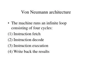
Load Balanced Birkhoff-von Neumann Switches. Cheng-Shang Chang, Duan-Shin Lee and Chi-Yao Yue presented by Prashanth Pappu. OPP. OPP. OPP. IPP. IPP. IPP. Controller. High Performance Switches. Non-blocking crossbar Fixed time slot, fixed size cell

E N D
Load Balanced Birkhoff-von Neumann Switches Cheng-Shang Chang, Duan-Shin Lee and Chi-Yao Yue presented by Prashanth Pappu
OPP OPP . . . OPP IPP IPP . . . IPP Controller High Performance Switches • Non-blocking crossbar • Fixed time slot, fixed size cell • Parallelism, memory speed = line rate. • Quadratic complexity but concentrated in a single chip set. • Centralized scheduler
Centralized Schedulers • VOQs to avoid HOL blocking. • Equivalent to finding a matching on a bipartite graph (Anderson et al) • McKeown et al. – 100% throughput with MWM. • 10Gb/s line rate implies 40 ns for scheduling. • Maximal size matching algorithms (PIM, iSLIP) • More ports and faster line rates makes it harder to implement scheduling algorithms.
Overview • New scheduling algorithm (based on Birkhoff-von Neumann decomposition) – “On service guarantees for input buffered crossbar switches: a capacity decomposition approach by Birkhoff and von Neumann”, IEEE IWQoS’99. • Birkhoff-von Neumann switches are not practical. • Load balanced Birkhoff-von Neumann switch – “Load Balanced Birkhoff-von Neumann Switches, Part I: One-stage Buffering”, Computer Communications. • Mis-sequencing problem and solutions – “Load Balanced Birkhoff-von Neumann Switches, Part II: Multi-stage Buffering”, Computer Communications and I. Keslassy and N. Mckweon “Maintaining Packet Order in Two Stage Switches”, IEEE Infocom, 2002. • Providing guaranteed rate services (The actual paper!) – “Providing guaranteed rate services in the load balanced Birkhoff-von Neumann Switches”, IEEE Infocom 2003. • Talk presents only algorithms + results – proofs.
Birkhoff-von Neumann Switch • Crossbar configuration is a permutation matrix, P. • 4x4 switch, input 1-output 4, input 2-output 1 etc. • Input rate matrix is admissible.
Birkhoff-von Neumann Switch • Can any admissible rate matrix be serviced? • How do we map rate matrix to a sequence of permutation matrices? (Change in pov as opposed to finding matching on bipartite graph) • Express as convex combination of permutation matrices. • Obtain the decomposition and schedule each permutation matrix proportional to its weight.
Birkhoff-von Neumann Switch • (von Neumann 1953) Transform the doubly substochastic rate matrix to a doubly stochastic matrix. • (Birkhoff 1946) Decompose doubly stochastic rate matrix to weighted sum of permutation matrices. • (PGPS) Use simple packet scheduling algorithm (WFQ) to determine which permutation matrix should be used to configure crossbar.
Example • von-Neumann conversion. • Pivots around (1,2), (2,1), (2,2) etc. • There are other (fairer) ways to obtain this conversion. R = R’ =
Example +0.4 = 0.4 R’ = +0.2
Not practical • Birkhoff-von Neumann decomposition is non-trivial with O(N4.5) complexity, though required only when rates change. • Need to know rate matrix. • Memory : O(N2) permutation matrices. • Does not support multicast. • Solution – Load balanced Birkhoff-von Neumann switch.
. . . . . . Load balancing stage BvN switch Load balanced BvN switch • We know decomposition is easy for uniform Bernouli i.i.d traffic. • Use a first stage that load balances traffic to second stage! • First stage uses permutation matrices generated from a one-cycle permutation matrix. (Input i connects to output (n+i) modulo N at time n.)
Second stage (Switching) • Traffic from first stage is instantly transferred to buffers at second stage. • With balanced traffic, second stage can also use a deterministic sequence of cyclical permutation matrices. (Input j is connected to output ((n-j) modulo N) at time n.) • Both stages are identical, complexity of scheduling algorithm O(1). • Low hardware complexity. • 100% throughput (under a mild technical condition)
Load balanced BvN switch (multi-buffered) • Problem of mis-sequencing of packets. • Packets are distributed on arrival times – no bound on a resequencing buffer. • Use load-balancing and re-sequencing buffers. • Load-balancing based on flows and not according to arrival times.
FCFS with jitter control • Flow splitter sends packets from same flow in round robin fashion to the N VOQs. • Causes packets of same flow to be split almost evenly among inputs of second stage. • Jitter control at second stage delays each packet to its maximum delay (targeted departure time is obtained from corresponding OQ switch) • Flows entering second stage are time-shifted versions of original ones.
FCFS with jitter control • Delay of a packet is bounded by sum of delay through the corresponding OQ switch and (N-1)Lmax + NMmax. • Essentially delay < 2N for unicast traffic. • Size of load balancing buffer bounded by NLmax. • Size of re-sequencing buffer bounded by NMmax. • Lmax (Mmax) is the maximum number of flows at an input (output).
Guaranteed Rate Services • Load balanced BvN switch provides best effort service. • How do we provide service guarantees? • Earliest Deadline First (EDF) based scheme.
EDF based scheme. • Same architecture as FCFS scheme with jitter control. • Targeted departure time is departure time of corresponding link with capacity equal to the guaranteed rate of the flow. • Packets served in EDF order at output buffer.
EDF scheme • Every packet of a guaranteed rate flow has a delay bound – targeted departure time + (N-1)Lmax + NMmax. • Resequencing and load balancing buffer bounded by NMmax.
Not discussed… • Full Frames First – an algorithm that prevents packets from being mis-sequenced. (Will be discussed in next paper presentation – “Scaling Internet routers using optics”) • Frame based scheme for guaranteed rate services – algorithm based on FFF for providing rate guarantees.