Download
1 / 22
230 likes | 472 Views
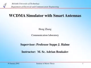
Helsinki University of Technology Department of Electrical and Communication Engineering. WCDMA Simulator with Smart Antennas Hong Zhang Communication laboratory Supervisor: Professor Seppo J. Halme Instructor: M. Sc. Adrian Boukalov. Helsinki University of Technology

E N D
Helsinki University of Technology Department of Electrical and Communication Engineering WCDMA Simulator with Smart Antennas Hong ZhangCommunication laboratory Supervisor: Professor Seppo J. Halme Instructor: M. Sc. Adrian Boukalov Seminar of Master Thesis
Helsinki University of Technology Department of Electrical and Communication Engineering Outline1. Background2. Different approach in WCDMA system modelling 3. Spreading in WCDMA4. RAKE Receiver and Multiuser Detection5. Smart Antenna in WCDMA 6. Simulation Results7. Conclusion Seminar of Master Thesis
Helsinki University of Technology Department of Electrical and Communication Engineering 1. Background The goal of 3G to provide a wide variety of communication services and high speed data access. WCDMA radio access technology for 3G The increasing demand of high capacity To provide high capacity technique Spreading Smart antenna RAKE receiver Multiuser detection tool Simulation Seminar of Master Thesis
Helsinki University of Technology Department of Electrical and Communication Engineering CDMA System Modelling 2. Different approach in WCDMA system modelling (1) With linear algebra knowledge Synchronous CDMA Modeling with AWGN channel Modeling with channel fading complexity Asynchronous CDMA Modeling with single path Modeling with multipath Modeling with smart antenna Seminar of Master Thesis
T T T β 1 β0 β N-1 h (t, , θ) = βj (t)( - j ) ( θ - θj) Helsinki University of Technology Department of Electrical and Communication Engineering 2. Different approach in WCDMA system modelling(2): Mobile radio channel Linear time-variant system β( ,t) DOA vmax max<<1 Multiple antennas in the receiver Quasi-stationary βt() h (t, , θ) = βj (t)( - j ) a( θ - θj) Uncorrelated scatters βi(t)( - i) GWSSUS Ray tracing model Sampled The tapped delay line model βj(t) ( - jT) Tapped delay line Wsmax<<1 Narrowband model β0(t) where βj (t) is the complex amplitude, j is path delay and θj is Direction Of Arrival, a( θ - θj) is the steering vectorGWSSUS: Gaussian Wide Sense Stationary Uncorrelated ScattersDOA: Direction Of Arrival Seminar of Master Thesis
Despreader unit K PN code Despreader unit 1 PN code Helsinki University of Technology Department of Electrical and Communication Engineering 2. Different approach in WCDMA system modelling(3): the fundamental structure Block diagram of the mobile transmitter for user k spreader PN code bk source of information xk encoder/ interleaver dk transmitter filter IF-RF upconverter D/A xk(t) Block diagram of the base station receiver sink 1 multiuser detector unit receiver front – end b yMF sink K r (t) Seminar of Master Thesis
Helsinki University of Technology Department of Electrical and Communication Engineering 2. Different approach in WCDMA system modelling(4):Discrete time base band uplink model for asynchronous CDMA The received signal Discrete time model base band uplink model for asynchronous CDMA system over a mobile radio channel u1 The output after matched filtering and correlating c1,1(i) ... c1,M(i) s1(i) p d1(i) u1 c2,1(i) ... c2,M(i) s2(i) p d2(i) . . . . . . . . . r n u1 cK,1(i) ... cK,M(i) sK(i) p dK(i) Seminar of Master Thesis
z D ’ waveform φ d B θ y α B-1 1 x Helsinki University of Technology Department of Electrical and Communication Engineering 2. Different approach in WCDMA system modelling(5):Discrete time base band uplink model for asynchronous CDMA with smart antenna The phase difference of the received signal between adjacent antenna elements The ULA with the direction of arrival (α, φ) indicated The received signal The output after matched filtering and correlating Seminar of Master Thesis
an an-1 an-2 an-r c1 c2 c3 cr Helsinki University of Technology Department of Electrical and Communication Engineering 3. Spreading in WCDMA (1) • Pseudo Random (PN) sequence: a bit stream of ‘1’s and ‘0’s occurring randomly, or almost randomly, with some unique properties. Linear shift register Seminar of Master Thesis
Helsinki University of Technology Department of Electrical and Communication Engineering 3. Spreading in WCDMA (2) : Spreading and scrambling at the uplink Spreading: to multiply the input information bits by a PN code and get processing gain, the chip level signal’s bandwidth is much wider than that of input information bits. It maintains the orthogonality among different physical channels of each user. Scrambling: to separate the signals from the different users. It doesn’t change the signal bandwidth. Each user has a unique scrambling code in the system. Channelization codes cos ( ω t) (Walsh/OVSF) Scrambling codes •Uplink spreading and modulation ( Cd ) (Gold) DPDCH P(t) ( Csc ) DPCCH P(t) j sin ( ω t) Channelization codes (Cc) (Walsh/OVSF) chip rate chip rate bit rate Suppressing interference WCDMA an interference limited system Selecting codes high autocorrelation low cross correlation Seminar of Master Thesis
• Walsh-Hadamard code Purpose: spreading Generation: code tree C 4,1 = ( 1 , 1 , 1 , 1 ) C 2,1 = ( 1 , 1 ) C 4, 2 = ( 1 , 1 , -1 , -1 ) C 1,1 = ( 1 ) C 4, 3 = ( 1 , -1 , 1 , -1 ) C 2,2 = ( 1 , 1 ) C 4,4 = ( 1 , -1, -1, 1 ) SF=2 SF=1 SF=4 Helsinki University of Technology Department of Electrical and Communication Engineering 3. Spreading in WCDMA (3) : Walsh-Hadamard code and Gold code • Gold codePurpose: scrambling Generation: modulo-2 sum 2 m-sequences Seminar of Master Thesis
Finger 1 Finger M ck,1(i)* ck,M(i)* Correlator Correlator sk(i)* sk(i)* y Helsinki University of Technology Department of Electrical and Communication Engineering 4. RAKE Receiver and Multiuser Detection(1): RAKE receiver r RAKE receiver: to collect the signal energy from different multipath components and coherently combine the signal Output : SNR Optimal for single user system • Combining methods Selection Combining Maximal Ratio Combining (MRC) Equal Gain Combining (EGC) Seminar of Master Thesis
User 1 RAKE User 2 RAKE r(t) Viterbi Algorithm User K RAKE Helsinki University of Technology Department of Electrical and Communication Engineering 4. RAKE Receiver and Multiuser Detection(2): Multiuser Detection WCDMA Multiple access Optimal Detector MAI High complex MUD design and analysis the digital demodulation in the presence of MAI Sub Optimal Detector LMMSE: Linear Minimum Mean Square Error MUD: multiuser detection MAI: multiple access interference Seminar of Master Thesis
Helsinki University of Technology Department of Electrical and Communication Engineering 4. RAKE Receiver and Multiuser Detection(3): Multiuser Detection y1 + - Decorrelating Detector s1(t) r(t) (synchronous) s2(t) (asynchronous) - y2 + Noise Decorrelating detector for 2 synchronous users Sub Optimal Detector LMMSE (synchronous) (asynchronous) Varying channel LMMSE: Linear Minimum Mean Square Error MUD: multiuser detection MAI: multiple access interference Adaptive MMSE algorithm- RLS algorithm with adaptive memory Seminar of Master Thesis
Broad-band beam-former structure Steering Delay •switched beam antenna array • adaptive antenna array r1 T T τ1 (φi,θi) Desired signal Desired signal w11 w12 w1M Interfering signal Interfering signal y(t) rB T T τB (φi,θi) wB1 wB2 wBM Error signal - Weight control + Reference signal Helsinki University of Technology Department of Electrical and Communication Engineering 5. Smart Antenna in WCDMA (1) Smart Antennaconsists of antenna array, combined with signal processing in space (or time) domain Type Seminar of Master Thesis
Helsinki University of Technology Department of Electrical and Communication Engineering 5. Smart Antenna in WCDMA (2): Beamforming schemes MMSE: mimimize mean square error LCMV: Linearly Constrained Minimum Variance RLS: recursive least squares Conventional Beamforming wc = (1 /B ) s MMSE w = R-1 p Max SNR Rn-1Rsw = λmax w LCMV w = R-1c[cHR-1c]-1g Statistically Optimum Beamforming RLS algorithm with adaptive memory Adaptive Beamforming Seminar of Master Thesis
spreading scrambling chip rate chip rate bit rate Pulse shaping filter Channel h(1)(t) d1(i) ( user 1) Modulation (BPSK) d2(i) ( user 2) Pulse shaping filter Channel h(2)(t) Modulation (BPSK) MAI dK(i) ( user K) Pulse shaping filter Channel h(K)(t) Modulation (BPSK) Helsinki University of Technology Department of Electrical and Communication Engineering 6. Simulation (1)• Simulation block diagram of transmitter in WCDMA uplink Seminar of Master Thesis
Helsinki University of Technology Department of Electrical and Communication Engineering 6. Simulation (2) • Simulation block diagram of 2- D RAKE receiver in uplink WCDMA User 1 Spatial processing Temporal processing (RAKE) ● W1,M ● ● ● *1(t-τM) ● Multiuser Detection W1,2 ● ● W1,1 ● *1(t-τ2) ● ● ● *1(t-τ1) ● n(t) User K ● WK,M ● ● *1(t-τM) ● WK,2 ● ● WK,1 ● *1(t-τ2) ● ● *K(t-τ1) Seminar of Master Thesis
Helsinki University of Technology Department of Electrical and Communication Engineering 6. Simulation(3) • Channel: ray tracing channel model The simulation area : the campus area of Dresden University of Technology. Simulation area MS location BTS Seminar of Master Thesis
Helsinki University of Technology Department of Electrical and Communication Engineering 6. SimulationResults(4) • Assume all the users randomly access the channel, and the PN code of each user is acquired and synchronized perfectly in the base station. • Assume the number of fingers in RAKE receiver equal to the number of multipath components. • The channel parameters are updated symbol by symbol, i.e. channel varies with time. The system performance of 1-D RAKE and conventional matched filter receiver for single user System performance of 1- D RAKE receiver with Decorrelating Detector and linear MMSE DD: Decorrelating Detector LMMSE SA: smart antenna for spatial processing PG: Processing Gain MUD: Multiuser Detection Seminar of Master Thesis
Helsinki University of Technology Department of Electrical and Communication Engineering 6. SimulationResults(5) The system performance of 1-D RAKE with spreading by Walsh codes and scrambling by Gold codesspreadingand scrambling by random codes The system performance of 1-D RAKE with different Processing Gain The system performance of 2-RAKE receiver with RLS algorithm with adaptive memory for spatial processing and MUD 2 antenna elements 3 active users 3 antenna elements 3 active users DD: Decorrelating Detector LMMSE SA: smart antenna for spatial processing PG: Processing Gain MUD: Multiuser Detection Seminar of Master Thesis
Helsinki University of Technology Department of Electrical and Communication Engineering 7. Conclusion • The simulation results have shown that spreading, RAKE receiver, multiuser detection and smart antenna are very important techniques to improve WCDMA system performance and increase system capacity. Seminar of Master Thesis