Download

1 / 76
770 likes | 907 Views
U.S. and International Satellite Characterization in Support of Global Earth Observation. Greg Stensaas, USGS 10 May 2007. Project Introduction. USGS Remote Sensing Technologies (RST) Project calval.cr.usgs.gov Greg Stensaas - (605) 594-2569 - stensaas@usgs.gov

E N D
U.S. and International Satellite Characterization in Support of Global Earth Observation Greg Stensaas, USGS 10 May 2007
Project Introduction • USGS Remote Sensing Technologies (RST) Project • calval.cr.usgs.gov • Greg Stensaas - (605) 594-2569 - stensaas@usgs.gov • Gyanesh Chander - (605) 594-2554 - gchander@usgs.gov • Project provides: • characterization and calibration of aerial and satellite systems in support of quality acquisition and understanding of remote sensing data, • and verifies and validates the associated data products with respect to ground and atmospheric truth so that accurate value- added science can be performed. • assessment of new remote sensing technologies • Working with many organizations and agencies; US and International
System/Product Characterization • System Characterization is related to understanding the sensor system, how it produces data, and the quality of the produced data • Imagery attempts to accurately report the conditions of the Earth's surface at a given the time. • Assessed by product characterization categories: • Geometric/Geodetic: The positional accuracy with which the image represents the surface (pixel coordinates vs. known ground points) • Spatial: The accuracy with which each pixel represents the image within its precise portion of the surface and no other portion • Spectral: The wavelengths of light measured in each spectral "band" of the image • Radiometric: The accuracy of the spectral data in representing the actual reflectance from the surface • Dataset Usability: The image data and understanding of the data is easily usable for science application
Joint Agency Commercial Imagery Evaluation (JACIE) 6th Annual Workshop held March 20-22, 2007 • USGS, NGA, USDA, and NASA Collaboration • Mark your calendars for March 2008!! • Workshop information @ http://calval.cr.usgs.gov/jacie.php • Enhanced scope to Satellite & Aerial sensors useful to the remote sensing community – U.S. and International systems • Independent assessment of product quality and usability • New applications and understanding of remotely sensed data
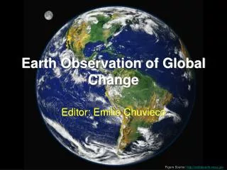
1986 100 km 1997 Landsat Importance to Science Amazonian Deforestation • Change is occurring at rates unprecedented in human history • The Landsat program provides the only inventory of the global land surface over time • at a scale where human vs. natural causes of change can be differentiated • on a seasonal basis • No other satellite system is capable/committed to even annual global coverage at this scale Courtesy TRFIC–MSU, Houghton et al, 2000.
U.S. Landsat Archive Overview(Marketable Scenes through September 25, 2006) • ETM+: Landsat 7 • 654,932 scenes • 608TB RCC and L0Ra Data • Archive grows by 260GB Daily • TM: Landsat 4 & Landsat 5 • 671,646 scenes • 336TB of RCC and L0Ra Data • Archive Grows by 40GB Daily • MSS: Landsat 1 through 5 • 641,555 scenes • 14TB of Data
Landsat Data Gap Study Team (LDGST) • The Earth observation community is facing a probable gap in Landsat data continuity before LDCM data arrive in ~2011 • A data gap will interrupt a 34+ yr time series of land observations • Landsat data are used extensively by a broad & diverse users • Landsat 5 limited lifetime/coverage • Degraded Landsat 7 operations • Either or both satellites could fail at any time: both beyond design life • Urgently need strategy to reduce the impact of a Landsat data gap • Landsat Program Management must determine utility of alternate data sources to lessen the impact of the gap & feasibility of acquiring data from those sources in the event of a gap • A Landsat Data Gap Study Team, chaired by NASA and the USGS, has been formed to analyze potential solutions
Team Membership Edward Grigsby, NASA HQ, Co- Chair Ray Byrnes, USGS HQ, Co- Chair Garik Gutman, NASA HQ, Co- Chair Jim Irons, NASA GSFC, Community Needs Working Group Lead Bruce Quirk, USGS EDC, System Capabilities Working Group Lead Bill Stoney, Mitretek Systems, Needs-to-Capabilities Working Group Lead Vicki Zanoni, NASA HQ Detail, Team Coordinator and Synthesis Working Group Lead Mike Abrams, JPL Bruce Davis, DHS (NASA detailee) Brad Doorn, USDA FAS Fernando Echavarria, Dept. of State Stuart Frye, Mitretek Systems Mike Goldberg, Mitretek Systems Sam Goward, U. of Maryland Ted Hammer, NASA HQ Chris Justice, U. of Maryland Jim Lacasse, USGS EDC Martha Maiden, NASA HQ Dan Mandl, NASA GSFC Jeff Masek, NASA GSFC Gran Paules, NASA HQ John Pereira, NOAA/NESDIS Ed Sheffner, NASA HQ Tom Stanley, NASA SSC Woody Turner, NASA HQ Sandra Webster, NGA Diane Wickland, NASA HQ Darrel Williams, NASA GSFC
Team Strategy Objective • Recommend options, using existing and near-term capabilities, to store, maintain, and upgrade science-quality data in the National Satellite Land Remote Sensing Data Archive • Consistent with the Land Remote Sensing Policy Act of 1992 Approach • Identify data “sufficiently consistent in terms of acquisition geometry, spatial resolution, calibration, coverage characteristics, and spatial characteristics with previous Landsat data…” • Consistent with Management Plan for the Landsat Program Process • Identify acceptable gap-mitigation specifications • Identify existing and near-term capabilities • Compare capabilities to acceptable specifications • Synthesize findings and make recommendations
Team Assumptions • Assume 2007 Landsat 7 failure for planning purposes • Assume limited lifetime and capability for Landsat 5 • Focus on data acquisition vs. building a satellite • Address DOI responsibility to store, maintain, and upgrade science-quality data in the National Satellite Land Remote Sensing Data Archive (NSLRSDA) • OLI data available no earlier than 2010 • LDCM data specification used to define team’s data quality and quantity goals • Landsat 7 unrestricted data policy will serve as the model for acquired data
TOOLS FOR OBSERVING THE LAND Resolution and coverage for different needs…. “Moderate Resolution Land Imaging (5-120m)” …. PLUS RADAR, MAGNETICS, MICROWAVE, ETC., plus airborne and in situ methods
Requirements and Capabilities Analysis • LDCM Data Specification (“Goal”) has been vetted by science and applications communities, and supports the full range of Landsat applications • Obtaining data identical to LDCM from existing systems is not possible • Minimum acceptable specifications were derived to support basic global change research given available sources of Landsat-like data • 2x Annual Global Coverage • Spatial Resolution • Spectral Coverage • Data Quality • Systems Considered • IRS ResourceSat – 1, 2 (India) • CBERS – 2, 2A, 3, 4 (China & Brazil) • Rapid Eye – 1, 2, 3, 4, 5 (Germany) • DMC (Algeria, Nigeria, UK, China) • Terra/ASTER (US & Japan) • High-resolution U.S. commercial systems • IKONOS, Quickbird, OrbView-3 • ALOS (Japan) • SPOT – 4, 5 (France) • EO-1/ALI (US)
Landsat Synoptic Coverage Landsat ALI ResourceSat LISS III ALOS ASTER/SPOT ResourceSat AWiFS CBERS MUXCAM CBERS IRMSS RapidEye Note: For purposes of scene size comparison only. Locations do not represent actual orbital paths or operational acquisitions. CBERS-3,4 WFI-2 DMC
Landsat Data Gap Synopsis • There is no substitute for Landsat • Single source of systematic, global land observations • Alternate sources may reduce the impact of a Landsat data gap • Data quality and operational capability of potential candidate systems is currently being verified • USGS currently working with ISRO ResourceSat-1 (India) and CAST/INPE CBERS (China Brazil) • Landsat data gap mitigation efforts could serve as prototype for Integrated Earth Observing System (IEOS -- U.S. contribution to GEOSS) • Implementation plan correlates with IEOS Global Land Observing System concept • Several systems could meet special regional acquisition needs during some or all of the data gap period
Data Gap Study Team Management • Landsat Data Gap Study Team (LDGST) • Developing a strategy for providing data to National Satellite Land Remote Sensing Data Archive for 1-4 years • Policy and Management Team – Ed Grigsby and Ray Byrnes • Technical Team – Chaired by Jim Irons • Data Characterization Working Group (DCWG) • Technical group from three field centers (USGS EROS, NASA GSFC, NASA SSC) to evaluated data from IRS-P6 and CBERS-2 sensors • Tiger Team Charter • The tiger team is charged with developing & analyzing a set of technical & operational scenarios for receiving, ingesting, archiving, and distributing data from alternative, Landsat-like satellite systems. • The tiger team will conduct trade studies & assess the risk of the various scenarios & provide rough order magnitude costs for the alternatives
Overview of the CBERS-2 sensorsCross-Calibration of the L5 TM and the CBERS-2 CCD sensor
China Brazil Earth Resources Satellite -CBERS • CBERS-1, was launched on Oct. 14, 1999 • The spacecraft was operational for almost 4 years • The CBERS-1 images were not used by user community • On Aug. 13, 2003, CBERS-1 experienced an X-band malfunction causing an end of all image data transmissions • CBERS-2 (or ZY-1B) was launched successfully on Oct. 21, 2003 from the Taiyuan Satellite Launch Center • The spacecraft carries the identical payload as CBERS-1 • CBERS Orbit • Sun synchronous • Height: 778 km • Inclination: 98.48 degrees • Period: 100.26 min • Equator crossing time: 10:30 AM • Revisit: 26 days • Distance between adjacent tracks: 107 km
CBERS- Sensor Compliment • CBERS satellite carries on-board a multi sensor payload with different spatial resolutions & collection frequencies • HRCCD (High Resolution CCD Camera) • IRMSS (Infrared Multispectral Scanner) • WFI (Wide-Field Imager) • The CCD & the WFI camera operate in the VNIR regions, while the IRMSS operates in SWIR and thermal region • In addition to the imaging payload, the satellite carries a Data Collection System (DCS) and Space Environment Monitor (SEM)
Pay load Module (16) CCD (14) China IRMSS (7) China WFI (20) Brasil Data Transmission China Data collection Brasil Service Module (1) Structure Brasil Thermal Control China Attitude and Orbit Control China Power supply Brasil On-board computer China Telemetry Brasil Work Share (70% China, 30% Brazil)
High Resolution CCD (HRCCD) • The HRCCD is the highest-resolution sensor offering a GSD of 20m at nadir (Pushbroom scanner) • Quantization: 8 bits • Ground swath is 113 km with 26 days repeat cycle • Steerable upto +/- 32o across track to obtain stereoscopic imagery • Operates in five spectral bands - one pan & four VNIR • CCD has one focal plane assembly • The signal acquisition system operates in two channels • Channel 1 has Bands 2, 3, 4 • Channel 2 has Bands 1,3,5 • Four possible gain settings are 0.59, 1.0, 1.69 & 2.86
Infrared Multispectral Scanner (IRMSS) • The IRMSS is a moderate-resolution sensor offering a GSD of 80m (pan/SWIR) & 160m (thermal) • Quantization: 8 bits • Ground swath is 120 km with 26 days repeat cycle • Operates in four spectral bands - one pan, two SWIR & one thermal • The four spectral bands has eight detector staggered arrays mounted along track • IRMSS has three focal plane assemblies • The Pan band (Si photodiodes detectors) is located on the warm focal plane • The SWIR bands & the thermal band (HgCdTe detectors) are located on cold focal planes with cryogenic temps of 148K & 101K respectively • Four of eight thermal detectors are spare
IRMSS On-board Calibrator • The IRMSS incorporates an onboard radiometric calibration system • Internal Calibrator (IC) and a Solar calibrator • The IC includes cal lamp & blackbody that acquire real time cal data during the scan-turn around interval • During that time a rotating shutter is driven to prevent the Earth flux from being incident on the focal plane and the flux from calibration lamp and blackbody is reflected to the focal plane • The lamp calibrator has 4 operation states corresponding to different flux output (each state lasts about 16 seconds) • The solar calibrator is designed to provide cal reference with the Sun upon ground command • As the satellite passes over the north polar regions, the solar cal collects the solar flux & reflects it onto the Pan/SWIR band detectors • The solar calibration also provides a check on the stability of the on-board lamp calibration (It is performed once every 13 day)
Wide-Field Imager (WFI) • The WFI camera provides a synoptic view with spatial resolution of 260m • Ground swath is 885km with 3-5 days repeat cycle • Operates in two spectral bands – (Band 3 & 4) • 0.63 - 0.69 μm (red) and 0.77 - 0.89 μm (infrared) • Similar bands are also present in the CCD camera providing complementary data
CBERS-2 IRMSS CB2-IRM-157/124, 24/3/2004, Catanduva (Brazil) CBERS-2 CCD image, Louisiana Obtained from on-board data recorder
Striping in the CCD data B1 B2 B3 B4
Absolute Calibration Coefficients • Independent studies are carried out by INPE & CRESDA • INPE used calibration sites in the west part of State Bahia • CRESDA used Gobi desert (Dunhuang) test site in China L* = DNn / CCn L* = spectral radiance at the sensors aperture W/(m2.sr.um) DN = Digital number extracted from the image in band n CCn = absolute calibration coefficient for band n
CBERS-2 CCD absolute calibration accuracy relative to L5 TM • Data continuity within the Landsat Program requires consistency in interpretation of image data acquired by different sensors • A critical step in this process is to put image data from subsequent generations of sensors onto a common radiometric scale • To evaluate CBERS-2 CCD utility in this role, image pairs from the CBERS-2 CCD & L5 TM sensors were compared • The cross-calibration was performed using image statistics from large common areas observed by the two sensors • It is very difficult to get coincident image pairs from the two satellites (different WRS)
L5 TM and CBERS-2 CCD Image Pairs Gobi (Dunhuang) desert test site Data acquired on Aug 25, 2004 (20 min apart) L5 TM WRS Path = 137 Row = 032 Nadir looking CBERS-2 CCD Path = 23 Row = 55side-looking (off-nadir-look-angle=-6.0333) L5 TM WRS Path = 219 Row = 076 Nadir looking Acquisition Date:Dec 29, 2004 CBERS-2 CCD Path = 154 Row = 126 Acquisition Date: Dec 30, 2004 L5 TM WRS Path = 217 Row = 076 Nadir looking Acquisition Date:Nov 16, 2005 CBERS-2 CCD Path = 151 Row = 126 Acquisition Date: Nov 16, 2005
CBERS-2 test downlink at USGS EROS • CBERS-2 test downlink at USGS EROS ground station was very successful • This is the first time that the CBERS-2 satellite data was down linked in a country other than China and Brazil • “CBERS in a box” works • The CBERS-2 capture and processing system is a small computer that can perform the following tasks • ingest the raw data • show the image data in a “moving window” display • record the raw data in the computer’s hard disk • process the raw data to level 1 products • generate quick looks to populate the Data Catalog of the system • make the level 1 data available to the users
The first China-Brazil Earth Resources Satellite (CBERS-2) data downlink at USGS Center for EROS in support of the Landsat Data Gap Study
The USGS Center for EROS Director, R.J. Thompson, visiting with Jose Bacellar from Brazilian National Institute for Space Research (INPE) after a successful China-Brazil Earth Resources Satellite (CBERS-2) data downlink
Challenges and Future Plans • CBERS-2 High Density Data Recorder (HDDR) is not in use due to power limitations • The IRMSS stopped working in Apr 2005 due to power supply failure • Limited coincident Landsat/CBERS image-pairs • Limited data distribution policies outside the country • Limited documentation available • No L7 data downlink in Brazil • CBERS-2B test downlink at USGS EROS (CBERS cal visit to EROS 2/20/07) • Analyze IRMSS data • Evaluate the raw data (artifacts, noises) • Evaluate the relative calibration of the CCD data • Evaluate Bias estimates • Night time acquisitions • Perform similar cross-calibration experiment • Data processed from INPE • Data processed from CRESDA • Same datasets processed at INPE and CRESDA • Temporal scale (image pairs from 2003-2005) • Perform joint field Vicarious calibration campaign
Overview of the IRS-P6 SensorsCross Calibration of the L7 ETM+ and L5 TM with the IRS-P6 AWiFS and LISS-III Sensors
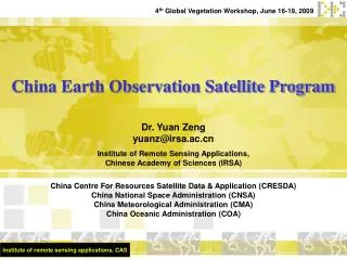
Resourcesat-1 (IRS P6) • The RESOURCSAT-1 satellite was launched in to the polar sun-synchronous orbit (altitude of 817 km) by PSLV-C5 launch vehicle on October 17, 2003 with a design life of 5 years • RESOURCSAT-1 is also called IRS-P6 • Most advanced Remote Sensing Satellite built by ISRO • Tenth satellite of ISRO in IRS series • Other ISRO operational satellites are IRS 1-C, IRS 1-D, IRS P-2, IRS P-3
ResourceSat-1 Overview • RESOURCESAT-1 carries three sensors • High Resolution Linear Imaging Self-Scanner (LISS-IV) • Medium Resolution Linear Imaging Self-Scanner (LISS-III) • Advanced Wide Field Sensor (AWiFS) • All three cameras are “push broom” scanners using linear arrays of CCDs • RESOURCESAT-1 also carries an On-board Solid State Recorder (OBSSR) with a capacity of 120 Giga-Bits to store the images
Advanced Wide Field Sensor (AWiFS) • The AWiFS with twin cameras is a moderate-resolution sensor offering a GSD of 56m at nadir • Quantization: 10 bits • Combined ground swath is 740km with five day repeat cycle • Operates in four spectral bands – three VNIR one SWIR • VITAL FACTS: • Instrument: Pushbroom • Bands (4): 0.52-0.59, 0.62-0.68, 0.77-0.86, 1.55-1.70 µm • Spatial Resolution: 56 m (near nadir), 70 m (near edge) • Radiometric Resolution: 10 bit • Swath: 740 km • Repeat Time: 5 days • Design Life: 5 years
AWiFS Sensor Collection Mode The AWiFS camera is split into two separate electro-optic modules (AWiFS-A and AWiFS-B) tilted by 11.94 degrees with respect to nadir
Medium Resolution Linear Imaging Self-Scanner (LISS-III) • The LISS-III is a medium resolution sensor offering a GSD of 23.5m • Quantization: 7 bits (SWIR band 10 bits – selected 7 transmitted) • Ground swath is 141 km with 24 day repeat cycle • Operates in four spectral bands - three VNIR one SWIR • Each band consists of a separate lens assembly & linear array CCD • The VNIR bands use a 6000 element CCD with pixel size 10x7 microns • The SWIR band uses a 6000 element CCD with pixel size 13x13 microns • The data from the VNIR bands are digitized to 7 bits while the data from SWIR band are digitized to 10 bit • The VNIR bands could be operated in any one of the four selectable gains by command, while the SWIR band is configured with single gain setting covering the full dynamic range
Conversion to Radiance L* = (Lmax-Lmin) Qcal + Lmin Qcalmax Where • L* = spectral radiance at the sensors aperture W/(m2.sr.um) • Qcal = Calibrated Digital Number • Qcalmax = maximum possible DN value • 255 for LISS-IV & LISS-III products, • 1023 for 10-bit AWiFS and 255 for 8-bit AWiFS products • Lmax & Lmin = scaled spectral radiance (provided in the header file) • For GeoTIFF products, these values are found in the Image Description field of the GeoTIFF header • For Fast Format products, values are in the HEADER.DAT • For LGSOWG products, values are in the leader file
Header File Information (Lmax & Lmin) LISS-IV Mono Band 3: On board gain number for band 3 ......................... 3 Minimum / maximum radiance for band 3 [mw/cm2/str/um] ... 0.00000 9.92230 LISS-III: On board gain number for band 2 ......................... 3 On board gain number for band 3 ......................... 3 On board gain number for band 4 ......................... 3 On board gain number for band 5 ......................... 2 Minimum / maximum radiance for band 2 [mw/cm2/str/um] ... 0.00000 12.06400 Minimum / maximum radiance for band 3 [mw/cm2/str/um] ... 0.00000 15.13100 Minimum / maximum radiance for band 4 [mw/cm2/str/um] ... 0.00000 15.75700 Minimum / maximum radiance for band 5 [mw/cm2/str/um] ... 0.00000 3.39700 AWiFS-A camera (A&C quadrant scenes): On board gain number for band 2 ......................... 8 On board gain number for band 3 ......................... 9 On board gain number for band 4 ......................... 8 On board gain number for band 5 ......................... 9 Minimum / maximum radiance for band 2 [mw/cm2/str/um] ... 0.00000 52.34000 Minimum / maximum radiance for band 3 [mw/cm2/str/um] ... 0.00000 40.75000 Minimum / maximum radiance for band 4 [mw/cm2/str/um] ... 0.00000 28.42500 Minimum / maximum radiance for band 5 [mw/cm2/str/um] ... 0.00000 4.64500 AWiFS-B camera (B&D quadrant scenes): On board gain number for band 2 ......................... 8 On board gain number for band 3 ......................... 9 On board gain number for band 4 ......................... 8 On board gain number for band 5 ......................... 9 Minimum / maximum radiance for band 2 [mw/cm2/str/um] ... 0.00000 52.34000 Minimum / maximum radiance for band 3 [mw/cm2/str/um] ... 0.00000 40.75000 Minimum / maximum radiance for band 4 [mw/cm2/str/um] ... 0.00000 28.42500 Minimum / maximum radiance for band 5 [mw/cm2/str/um] ... 0.00000 4.64500