Download
1 / 20
230 likes | 609 Views
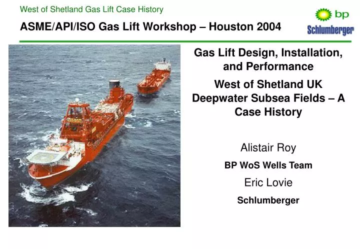
ASME/API/ISO Gas Lift Workshop – Houston 2004. Gas Lift Design, Installation, and Performance West of Shetland UK Deepwater Subsea Fields – A Case History Alistair Roy BP WoS Wells Team Eric Lovie Schlumberger. West of Shetlands Location Map. Atlantic Ocean (60degN, 4degW)

E N D
ASME/API/ISO Gas Lift Workshop – Houston 2004 Gas Lift Design, Installation, and Performance West of Shetland UK Deepwater Subsea Fields – A Case History Alistair Roy BP WoS Wells Team Eric Lovie Schlumberger
West of Shetlands Location Map • Atlantic Ocean (60degN, 4degW) • UKCS blocks 204/19,20,24a,25a,25b 205/16,21b • 380 - 500m (1,200 – 1,650ft) water • 190km (120miles) West of Shetland
Field and Fluid Descriptions • High quality sands • Porosity ~ 23- 27 % • Permeability (500 - 2000mD) • Original pressure 2,800 – 3,500 psi • Productivity Indices 12 – 50bbl/d/psi • Faulted anticline with lateral stratigraphic trapping. • Multiple reservoir units • 25 - 27° API oil, 0.5 - 4cP viscosity • GOR 330 – 550scf/bbl • Bubble Point 2,500 – 3,100psi • Temperature 140 degree F
Artificial Lift Selection in Deepwater Subsea Development • Gas lift selected as artificial method due to high reliability • ESPs perceived as requiring a significant number of workovers • Subsea work-overs are expensive, in the region of £3MM each. • Jet pumps / hydraulic pumps more robust, but still less reliable than gas lift • Jet pumps seen as less efficient in high productivity index wells • Gas lift offers flexibility to mitigate variable well performance • HP compressor and gas injection riser required for gas disposal (to limit flaring) • Availability of HP gas further increases GL reliability • Single point gas lift via orifice valve • No unloading valves required • Second mandrel and dummy valve included in early completions to provide redundancy when orifice valve set deeper than wire-line depth
Completion and GL Design Interaction • Completion objectives • Sustain liquid production rates of 5,000 – 20,000bpd at water cuts up to 95% • Completion reliability for 20 year life of field (no interventions) • Quick and simple completion to run • Tubing size selection • Without gas lift 4-1/2” tubing would have been selected, based on well stability and maximising recovery prior to well dying at high water cut. • 5-1/2” tubing (and in some cases 7”) can be selected with GL availability • Larger tubing and gas lift significantly impacts project economics • Gas lift valve placement • Orifice valve run as deep as possible to maximise production • Orifice frequently run at a depth inaccessible with wireline • Dummy valve run at wire-line accessible depth as contingency
Production Well Completion Schematic • Schiehallion Producer – 7” tree crossing over to 5-1/2” SCSSV and tubing • Dual bore tree with 2-3/8” annulus string • Simple completion with no space-out required • GLV and gauge run as deep as possible, just above packer • GLV run approx 30m above gauge to reduce vibration effect on gauge
Gas Lift System Overview • Foinaven gas lift parameters • Available GL pressure 220barg (3190psi) at wellhead • Theoretical maximum gas discharge pressure (at FPSO) 210barg • Available gas compression capacity 95MMscf/day • Gas injection riser 8”, 2 x 8” GL lines, 2” annulus valves and pipework • Schiehallion gas lift parameters • Available GL pressure 174barg (2520psi) at wellhead • Theoretical maximum gas discharge pressure (at FPS0) 210barg • Available gas compression capacity 95MMscf/day • Gas Injection riser 8”, GL Lines 2 x 6” and 1 x 8”, 2” annulus valves and pipe-work • On occasion, lower Schiehallion pressure has resulted in shallower SPM depth • Lift gas composition 98%+ methane, 0.65SG, sweet with no H2S and 0.2% C02
Gas Compression Availability and Uses West of Shetland • Foinaven gas supply typically limited to 95mmscf/d; • Gas lift 50mmscf/d • 11mmscf/d fuel and flare • Gas disposal well 80mmscf/d capacity declining to 35mmscf/d when export started • 35MMscf/d gas export • Schiehallion gas supply typically limited to 95mmscf/d; • Gas lift 40mmscf/d • 12mmscf/d fuel and flare • Gas disposal well up to 70mmscf/d in past, but GI riser decommissioned in 2002 due to stress related fatigue and sea-water ingress. • 40MMscf/d gas export • Gas export to Magnus replaced gas re-injection in 2001/2002
Gas Lift & Production Optimisation • Full production system model constructed and maintained by Offshore Production Engineer • Gas lift allocation is critical to the optimisation process • Configuration is updated regularly and optimised for situations such as new well start-up • BHP gauges and well tests provide regular input for the optimisation
Foinaven Gas Lift Allocation • Foinaven Gas Supply for lift approx 50MMscf/d • Dry oil wells benefit from application of gas lift • Incremental oil of 1800bopd for 1MMscf/d gas • Production benefit from gas lift declines quickly over 3MMscf/d • With available gas and limited water handling capability, focus is on optimising dry wells first • Important to achieve stable flow using correct gas lift allocation – slugging production wells in a sand prone reservoir can lead to solids ingress
Completion and GL Valve Selection • Meet with completion objectives (20 year life) • 5-1/2” (and 7”) sidepocket mandrels • 13 Cr material • Ratings comparable to that of the tubing • 1-1/2” OD gas lift valves • Monel material, premium packing stacks • Robust, reliable operation with known gas passage capabilities • NOVA-15, typically 17/64” throat • Dual check, square edged orifice, typically 3/8” • No tubing to annulus integrity issues to date
Single vs Two Valve Installation • Initial completions included a second SPM with dummy valve at wireline depth • P27 TRSCSSV failure and insert valve run • TRSCSSV flapper removed with “Cannon” • Neither Bullet or flapper recovered from well • CT hung up in subsequent well interventions • Failed to drift upper SPM • Camera showed piece of flapper in SPM • Well flowed for period of time. On retrieving the insert SCSSV, lock from GLV was recovered with valve (along with pieces of original flapper) • Dummy valve / mandrel omitted from 2001 • GL straddles now adopted as contingency against gas lift problems
Well Start-Up Philosophy – Value of Gas Lift • Initial wells underbalanced by displacing to base oil and N2 and offloaded to rig • Significant rig time, cost and HSE exposure • Cleaning up wells to facilities • If not handled correctly cleaning up to FPSO can be damaging and expensive • Well clean-up for production an issue for FPSO • Initial practice was quick start-up at 100% choke to “collapse the sand face” • Combination of mud and completion brine causes trips in facilities, poor overboard water quality, lost production, damage to heaters • Current practice - offload annulus and tubing at controlled rate with gas lift and contain within flow line. • Flow line contents diverted for treatment, bypassing much of facilities • Production losses reduced and no damage to facilities • Annulus displaced at 15bar/hour (roughly 1bbl/m for offloading liquid via GLV)
GL Valve Unloading Trials • GL unloading trials performed at different flowrates • After 1000bbls of liquid at 1bpm valve was generally in good condition, no signs of damage on check valves, springs or orifice • After 1000bbls of liquid at 2bpm valve again valve was generally in good condition however the soft seat of the upper check showed a significant erosion effect that was operationally not acceptable. • Currently no tubing to annulus integrity issues on either field
Foinaven Well P11 Start-Up Problems • P11 start-up problematic, over 18 hours to offload well and bring on production • GLV too deep versus completion fluid gradient – unable to offload well at maximum GL pressure with 520m of riser full of normal production fluids. • Displaced riser using gassed out production well to lighten fluid column
P16 Gas Lift Valve for Gas Injection • Field production depends on gas disposal as only limited flaring allowed • Pre-EOR, production was heavily dependant on a single gas disposal well for each development • Foinaven injection well G31 lost injectivity in July 1998 • Well P16 was converted to gas injection but rate constrained in 5-1/2” tubing • Solution was to inject down tubing and annulus via GLV • 1mmscfd injection = 2500bopd. 20mmscf/d allowed field to maintain significant production • Decreasing GI well injectivity led to increased P16 utilisation
Gas Lift Related Problems West of Shetlands • A variety of minor problems encountered to date in different circumstances • Completion operations • P27 CT intervention resulted in stuck pipe across dummy GLV. Lesson Learned – do not run additional equipment “just in case” • Problems setting hydrostatic packer (on six wells). Initial diagnosis was that the packer had not set as annulus pressure kept rising, but believed to be GL back check not seating. Packer set at second attempt on all occasions. • Production operations • Gas lift orifice meters failed on a number of wells leading to in-accurate allocation • Gas lift capability lost on two Foinaven wells due to hydrates around tree area, eventually freed with Methanol • One ACV locked in fixed position resulting in 5mmscf/d GL being applied to P25 when 1 to 1.5mmscf is required
Summary and Future Competition for Gas Compression • Seven years field production has shown good operability and well management flexibility • The selection of gas lift as the artificial lift method fits very well with the simple completion design concept • Gas compression is now used for export as well as gas lift • As water cut increases, incremental oil rate reduces for each scf of lift gas. Gas export may become more valuable than gas lift • Other options being considered to free up compression capacity • Riser base gas lift • Sub sea booster pumps could be used to increase drawdown. Worries include long term reliability and sandface integrity.
ASME/API/ISO Gas Lift Workshop – Houston 2004 Questions ?