CEDAR PMT Array DCS
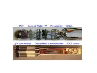
CEDAR PMT Array DCS. (Tim). Summary. Summary of DCS monitored parameters based on original scheme Major part of heat dissipation in electronics / PMTs at each light guide Recent developments (removal of pre-amps and provision of local NINO boards needs some consideration

CEDAR PMT Array DCS
E N D
Presentation Transcript
CEDAR PMT Array DCS (Tim)
Summary • Summary of DCS monitored parameters based on original scheme • Major part of heat dissipation in electronics / PMTs at each light guide • Recent developments (removal of pre-amps and provision of local NINO boards needs some consideration • Currently just a ‘monitoring’ system • Any control (eg. chiller) set manually or by dedicated systems (eg. Huber chiller control s/w) CEDAR DCS
DCS & DSS • Assumptions • Some software / hardware system exists to log range of parameters of different types. • Monitored data can be displayed via on-screen panels. • Monitored data logged at intervals to storage • Alarm events • Can have different levels of severity • Pass through into data stream • Require operator to RESET • There exists a separate Detector Safety System • Prevents failures causing BIG PROBLEMS! CEDAR DCS
CEDAR PMT ARRAY DCS CEDAR DCS
Evolution • Removal of pre-amps from light-guide arrays does not eliminate all heat sources (PMTs & custom PMT bases) • Still need (would like) temperature sensor at each light guide position (need to think about location) • Local NINO boards • Assume these are mounted within the PMT array enclosure but separated from the Light-guides (eg. on the sides). • Assume • Power ~ 30 mW/PMT channel = 8W per side • Two boards • One 4-wire T sensor per board • 4 extra 4 wire T sensors CEDAR DCS
Inventory of Monitored Parameters CEDAR DCS
Alarms • Critical – cause immediate power down of all LV & HV systems & automatic call to expert • Chiller Flow LOW • Chiller Outlet Pressure LOW or HIGH • Chiller Outlet Temp LOW or HIGH • PMT Encl. N2 Flow LOW (x2) • Warning - • Any (PMT Encl. Temp – CEDAR Temp) LOW or HIGH • Any (PMT Light Guide Temp – CEDAR Temp) LOW or HIGH • CEDAR gas pressure LOW or HIGH CEDAR DCS
DSS • May be more relevant for operation with H2 – but should think about it now • Should be a stand-alone system separate from DCS but should also send signal to DCS • A DSS alarm should result in an (automated) action which makes the system safe (primary concern is human safety) • DSS Inputs • H2 concentration within PMT array enclosures (2) • Enclosure door HV interlock (2) • ? CEDAR DCS
Remarks • Preliminary set of monitoring points defined • Need to review to make sure it’s the right list • No local DCS expertise • Need advice on DCS signal input modularity and types • Need software support to configure DCS databases & develop display panels, messages, alarm screens, etc.. • Would need DCS system operational locally during assembly of PMT arrays to check out individual sensor performance and to estimate suitable monitoring point measurement frequencies. CEDAR DCS