Download
1 / 31
310 likes | 493 Views
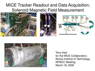
MICE Tracker Readout and Data Acquisition; Solenoid Magnetic Field Measurement. Terry Hart for the MICE Collaboration, Illinois Institute of Technology, NFMCC Meeting, March 18, 2008. Outline. Tracker Readout Introduction MICE Modifications Plans MICE Data Acquisition (DAQ)

E N D
MICE Tracker Readout and Data Acquisition; Solenoid Magnetic Field Measurement Terry Hart for the MICE Collaboration, Illinois Institute of Technology, NFMCC Meeting, March 18, 2008
Outline • Tracker Readout • Introduction • MICE Modifications • Plans • MICE Data Acquisition (DAQ) • DAQ Subsystems and Structure • Front End Electronics • Solenoid Magnetic Field Measurement • Initial Progress • Issues and Questions • Planning for Measurements Terry Hart, NFMC CM, March 18, 2008 2 of 29
MICE Tracker Acronyms • AFE-IIt – Analog Front End, Version II, with time • VLSB – VME LVDS Serdes Buffer • Versa Module Eurocard • Low Voltage Differential Signaling • Serialing/Deserializing • TriP-t – Trigger with Pipeline with time • VLPC – Visible Light Photon Counter Terry Hart, NFMC CM, March 18, 2008 3 of 29
AFE-IIt Boards IIT graduate student, Michael Wojcik, with a fully tested AFE-IIt board. Terry Hart, NFMC CM, March 18, 2008 4 of 29
AFE-IIt/D0/MICE Background • AFE-IIt boards are latest D0 tracker readout boards. • D0 and IIT arrangement • IIT students test boards for D0 • MICE received 22 boards • D0 firmware not fast enough for MICE muon rate • Substantial efforts from FNAL, IIT, and RAL to modify firmware for MICE Terry Hart, NFMC CM, March 18, 2008 5 of 29
Tracker Readout “Big Picture” • Scintillating Fiber Tracker (1 of 2) • Measures track trajectory and momentum • Placed in solenoid Terry Hart, NFMC CM, March 18, 2008 6 of 29
Tracker Readout “Big Picture” • Scintillating Fiber Tracker (1 of 2) • Measures track trajectory and momentum • Placed in solenoid • AFE-IIt boards (4 of 16) • Mounted on 4 VLPC cryostats • Record, format data from tracker • Hit fibers • Charge • Time Terry Hart, NFMC CM, March 18, 2008 6 of 29
Tracker Readout “Big Picture” • Scintillating Fiber Tracker (1 of 2) • Measures track trajectory and momentum • Placed in solenoid • AFE-IIt boards (4 of 16) • Mounted on 4 VLPC cryostats • Record, format data from tracker • Hit fibers • Charge • Time • VLSB boards (2 of 16) • Store formatted tracker data • Send data to MICE data acquisition (DAQ) Terry Hart, NFMC CM, March 18, 2008 6 of 29
MICE Time Scales, TriP-t • Average time between MICE triggers ~ 1700 ns, as short as 628 ns • TriP-t chips (16 on AFE-IIt board, 32 channels/chip) • Pipeline: stores analog charge and time data. (Event trigger formation takes ~ 1000 ns) • Analog buffer: upon trigger, data from pipeline and either • Digitized if 4-level buffer empty or • Placed in 4-level buffer if digitization of previous event not yet done TriP-t pipeline and buffer tested and working Terry Hart, NFMC CM, March 18, 2008 7 of 29
MICE AFE-IIt Firmware Modifications • Reduce time to digitize events • Enable TriP-t pipeline to collect data during digitization of event • Cycle through non-hit channels as quickly as possible • Digitization time will be reduced from 5700 ns to 1600 ns. • Implement TriP-t 4-level buffer • Board can accept, hold data in buffer while previous data digitizing • Increases recordable event rate for high input rate, short digitization time • Enable AFE-IIt clock to lock onto variable signal • ISIS clock frequency varies from 52.2 – 55.6 MHz each trigger Terry Hart, NFMC CM, March 18, 2008 8 of 29
600 480 360 240 120 0 1000 2000 3000 4000 Estimate of Recordable Muon Rate vs. Digitization Time, Buffer Level 4-level Buffering 3-level Buffering 2-level Buffering 1-level Buffering No Buffering Recordable Muon Rate (kHz) 9 of 29 Digitization Time (ns)
MICE Tracker Readout Plans • Near term: Cosmic ray tests at RAL • Putting together simplified firmware at FNAL • Perform full test at FNAL before shipment to RAL • About a few week time scale • Longer term: High rate MICE running • Sequentially add functionality • Zero suppression • 4-level buffer • Variable clock Terry Hart, NFMC CM, March 18, 2008 10 of 29
VLSB Boards 2 VLSB boards in VME crate Terry Hart, NFMC CM, March 18, 2008 11 of 29
VLSB Firmware VLSB = VME LVDS Serdes Buffer • Tracker data storage modules • Used for KEK test beam • Used by D0 for diagnostics Terry Hart, NFMC CM, March 18, 2008 12 of 29
VLSB Firmware Modifications • Data storage in memory banks • Before modifications • After modifications • Newly utilized registers for MICE DAQ • 4 registers, each one for each memory bank address of last data word • 1 register for number of events in spill • 1 register to initiate fast clear of memory banks after each spill … EVENT 1 EVENT 2 EVENT 3 zeros zeros … EVENT 1 EVENT 2 EVENT 3 Terry Hart, NFMC CM, March 18, 2008 13 of 29
Tracker Readout Status/Summary • AFE-IIt, VLSB firmware used for cryostat cassette characterization • AFE-IIt firmware development • Package for low rate cosmic ray testing being assembled • Firmware for high rate running in advanced development • VLSB firmware development done Terry Hart, NFMC CM, March 18, 2008 14 of 29
MICE DAQ Terry Hart, NFMC CM, March 18, 2008 15 of 29
MICE DAQ • MICE and ISIS Introduction • MICE Detector Front End Electronics • Software and MICE DAQ Architecture Terry Hart, NFMC CM, March 18, 2008 16 of 29
Systems for MICE DAQ • Target System: Titanium target inserted into ISIS proton beam produces pions decaying to muons. • RF Cavities: Eight 201 MHz cavities accelerate muons along MICE. • DAQ: Data from MICE trackers, calorimeter, Cherenkov detectors, and time-of-flight counters combined to form MICE events. ISIS proton spill → MICE target → pions,muons → MICE RF Cavities and Detectors … Terry Hart, NFMC CM, March 18, 2008 17 of 29
Detector Front End Electronics • Tracker • D0 AFE-IIt boards with firmware modificatons • Time-of-Flight • CAEN V1290 TDC with constant fraction discriminators • Calorimeter, Cherenkov • CAEN V1724 coupled with RC shapers Terry Hart, NFMC CM, March 18, 2008 18 of 29
MICE DAQ Hardware and Software • MICE DAQ software from DATE framework used by CERN experiment ALICE • ALICE = A Large Ion Collider Experiment • DATE = Data Acquisition and Test Environment • MICE detectors read out over VME. • Online data stream includes variables from MICE Control and Monitoring (MCM). • Data runs stopped for subsystem fault status or connection problem. Terry Hart, NFMC CM, March 18, 2008 19 of 29
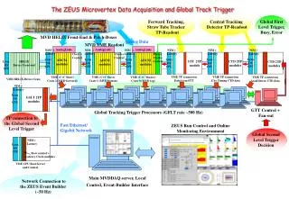
Data Flow MICE DAQ Architecture Trigger distribution VME Crates Calorimeter Tracker Time of Flight Counters Trigger+ Cherenkov Optical links Linux PCs GigaBit Switch 100 MegaBit Switch Remote Mass Storage Event Builder Online Online Storage MICE Control and MonitoringReadout Monitoring Run Control MCMSubnet Terry Hart, NFMC CM, March 18, 2008 20 of 29
MICE DAQ Summary • DAQ architecture determined • DATE framework • Detector FEEs read out by VME • Control and monitoring established • Detector FEEs under development • Tracker FEE software modified from D0 • FEE hardware for calorimeter, time-of-flight counters, and Cherenkov detectors set • Trigger signals and run modes established • MICE DAQ ready for initial beam. Terry Hart, NFMC CM, March 18, 2008 21 of 29
Solenoid Magnetic Field Measurement Terry Hart, NFMC CM, March 18, 2008 22 of 29
Solenoid Magnetic Field Measurement • MICE solenoid consists of 5 coils and iron shield • First solenoid expected at FNAL for magnetic field measurements in April • Measurements to be done with ZipTrack system. Terry Hart, NFMC CM, March 18, 2008 23 of 29
Work to Date • Simulations of field done with • Superfish (with and without iron shield) • FORTRAN numerical simulation • Analytic on-axis solution • Meetings with FNAL Alignment Group who will survey magnet and measure field Terry Hart, NFMC CM, March 18, 2008 24 of 29
Analytic and Numerical Simulations of Bz Along Solenoid Axis 5 magnet coils Shield location Blue points of numerical simulation hidden by red line on-axis analytic solution. Tesla Meters Terry Hart, NFMC CM, March 18, 2008 25 of 29
Superfish Simulation of Bz Along Solenoid Axis Terry Hart, NFMC CM, March 18, 2008 26 of 29
Effects of Iron Shield in Superfish Simulation No Shield Shield 10,000 1000 10,000 1000 Terry Hart, NFMC CM, March 18, 2008 27 of 29
Questions/Measurement Plan • Iron shield affecting magnetic field? • Measure field beyond ends of solenoid? (where time of flight counters will be) • Measurement precision sufficient for MICE tracking and emittance measurement? • Measure field in possible different modes? (different current densities in coils) Terry Hart, NFMC CM, March 18, 2008 28 of 29
Summary • Tracker firmware for cosmic ray tests at RAL being put together • Firmware for high rate MICE running well underway. • MICE DAQ is ready for initial MICE beam • Spectrometer field measurement and simulation program getting started Terry Hart, NFMC CM, March 18, 2008 29 of 29