Photometer Extended Source Photometry
Photometer Extended Source Photometry. Bernhard Schulz NHSC/ IPAC on behalf of the SPIRE ICC. Contents. Recap Point Source Photometry Choices Extended gain correction factors Zero-point corrected extended flux maps Convert point source map to extended source fluxes.

Photometer Extended Source Photometry
E N D
Presentation Transcript
Photometer Extended Source Photometry Bernhard Schulz NHSC/IPAC on behalf of the SPIRE ICC
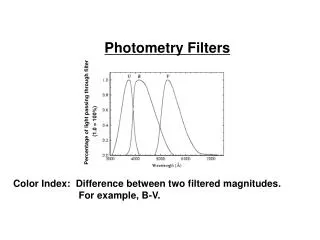
Contents • Recap Point Source Photometry • Choices • Extended gain correction factors • Zero-point corrected extended flux maps • Convert point source map to extended source fluxes. • Correction factors to take into account • Color correction • Omega correction • Aperture correction • Background correction • Derive aperture correction factors for semi extended sources • Uncertainties
Some Caveats The SPIRE photometric calibration is based on point sources. In this case extended emission is harder to calibrate and the errors are larger. This is a complex topic and calibration work on determining the beam profiles and solid angles is still ongoing, so we won’t always present final answers. However, we will show material and ways to make progress and how to work out solutions for specific problems.
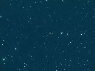
Recap Point Source Photometry Scan of detector PSWE8 over Neptune,obsid 1342187440 Point source flux The SPIRE calibration is based on point source photometry (Prime calibrator: Neptune) Standard SPIRE unit is Jy/beam When a detector is scanned centrally over a point source, the peak deflection of the signal timeline equals the brightness of the source. The spire broad-band photometry is quantified as monochromatic flux density at a reference wavelength (250, 350, 500mm) assuming a reference spectrum of nFn = const. For a different reference spectrum a color correction must be applied.
The Right Photometry Choice For point sources there are several choices and it depends a bit on the task at hand. For large and small extended sources there is only aperture photometry. The SPIRE Level 2 products fortunately already contain a product that comes in extended source units MJy/sr, ready for aperture photometry.
Extended Gain Correction Equal peaks Point-source maps Equal solid angles (integrals) Extended-source maps PSW: FWHMs are exaggerated Not all detector beam-profiles have the same width. Applying the Extended Gains equalizesthe detector areas (instead of the peaks). The numbers are provided in the SPIRE calibration tree. These gain factors should be applied before median subtraction, or destriping, and map-making.
Planck-HFI Herschel-SPIRE Level 1 Product Flux Timeline Planck All Sky Map Planck Beam Profile Offset Determination Image Convolution Map Maker Level 2 Product Extended Source Map Large Map Offset Correction Herschel-SPIRE/Planck-HFI X-Calib. • SPIRE and Planck-HFI overlap in SPIRE filters at 350 and 500mm (HFI 857 and 545 GHz filters). • Planck HFI is using photometric gains from Uranus and Neptune radiative models and zero-levels from correlation of HI (21cm) gas column density with CIB mean level added (Planck Collaboration VIII. 2013, In prep.) • Latest analysis shows very good correspondence of SPIRE and HFI photometric gains. We still multiply the HFI 545GHz map by 0965 for consistency. • The SPIRE standard pipeline uses fits to gain and color corrected HFI maps to provide absolute flux offsets in the extended flux map products.
Aperture Photometry See: http://herschel.esac.esa.int/twiki/bin/view/Public/SpirePhotometerBeamProfile • Aperture photometry sums up map pixels, i.e. expects the map signal in extended source units like MJy/sr, Jy/’’, or Jy/pixel. • The solid angle needed for the conversion is color dependent and was derived from large fine scan maps (1” pixels) of Neptune that go out to 700” radius. • The extended flux source maps in the HSA are converted for a n Fn=const. spectrum and corrections need to be applied to aperture photometry. • Color correction: • Source SED different from assumed reference spectrum n Fn=const. • Aperture correction • Correction for Flux lost outside of integration aperture. • Background correction • Correction for flux of the beam still inside of the annulus where backround is determined. • Omega correction • Correction for change in effective solid angle when source SED is different from n Fn=const.
Aperture Photometryon Point Sources Best to start with extended source map Convert Image Unit Task psrcPxW [Jy/beam] Color Correction Aperture Correction [Jy/pixel] Aperture Photometry Task [Jy/pixel] extdPxW [MJy/sr] Convert Image Unit Task For aperture photometry, starting with a point source map is not recommended but possible.
Aperture Correction Factors If background was perfectly known and subtracted. Take into account error due to beam residual in background estimation. Background Annulus Aperture Aperture r1 r1 90” 60” SBG Waper=S0..r1 S(r)*2*p*r*dr Waper=S0..r1 (S(r)-SBG) *2*p*r*dr Source profile aperCorr = Wtotal / Waper The same principles apply for both, point, and extended sources. Wtotal=SS(r)*2*p*r*dr
Aperture Photometry on Extended Sources extdPxW [MJy/sr] Aperture Correction Color+Omega Correction For a large bright source the aperture can be large and aperture correction is negligible. For a small faint source the aperture can not be too large and the aperture correction must be derived by modeling the source flux distribution to obtain precise results. [Jy/pixel] Aperture Photometry Task Convert Image Unit Task
Flux Uncertainty • Uncertainty in the derived flux • Includes the instrument • Confusion noise • (minimum of about 5 mJy for point sources) • Background estimate • ~10% of flux density for calibration uncertainty • 2% statistical reproducibility • 4% absolute level of Neptune model • (systematic) • 4% uncertainty in solid angle determination • (systematic) • This one may go away as it can in principle be bootstrapped out.