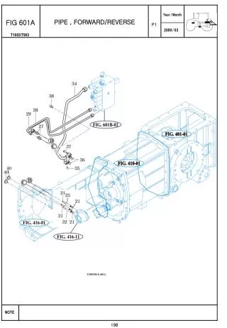
FIG 601 A
FIG 601 A. VALVE SUB, SHIFT. P1. 198. FIG 601B. VALVE SUB , MAIN. P1. 200. FIG 601C. VALVE SUB , MAIN ( OPTION :AQ ). P1. 202. FIG 602. DRAWBAR ASSY. P1. 204. FIG 603A. FILTER SUB, SUCTION. P1. 206. FIG 603B. GEAR PUMP ASSY. P1. 208. FIG 604. CASE , CYLINDER. P1. 210.
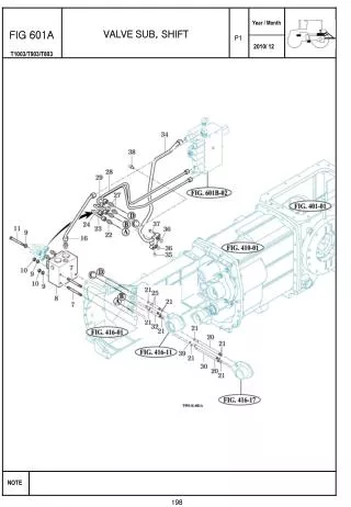

FIG 601 A
E N D
Presentation Transcript
FIG 601A VALVE SUB, SHIFT P1 198
FIG 601B VALVE SUB , MAIN P1 200
FIG 601C VALVE SUB , MAIN ( OPTION:AQ) P1 202
FIG 602 DRAWBAR ASSY P1 204
FIG 603A FILTER SUB, SUCTION P1 206
FIG 603B GEAR PUMP ASSY P1 208
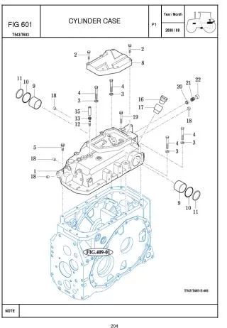
FIG 604 CASE , CYLINDER P1 210
FIG 605 ARM SUB, LIFT P1 212
FIG 606 MAIN CONTROL VALVE SUB P1 214
FIG 607A AUX VALVE & FILTER SUB P1 216
FIG 607B LEVER SUB, AUX P1 218
FIG 608A HITCH & 3-POINT LINK P1 220
FIG 608B LOWER LINK & LIFT ROD P1 222
FIG 609 HYDRAULIC PIPE & HOSES P1 224
FIG 610 JOYSTICK P1 226
FIG 611A LEVEL CONTROL SYSTEM (OPTION : AQ) P1 228
FIG 611B LEVEL CONTROL SYSTEM (OPTION : AQ) P1 230