Download
1 / 22
220 likes | 399 Views
Digital Transmission Key Learning Points Fundamentals of Voice Digitization Pulse Code Modulation Quantification Noise Multiplexed Digital Lines. 2.5.2 Digital Leased Circuits ( from public carriers) - supports high level of inter-site traffic, generally more

E N D
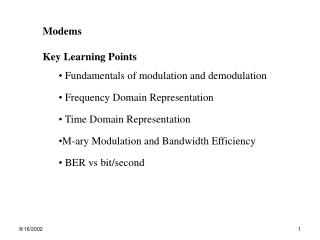
Digital Transmission • Key Learning Points • Fundamentals of Voice Digitization • Pulse Code Modulation • Quantification Noise • Multiplexed Digital Lines
2.5.2 Digital Leased Circuits (from public carriers) • - supports high level of inter-site traffic, generally more • expensive than modem based service • - provides direct digital connection between DTE’s • - basis of most private data & voice networks • goal: understand organization & capacity of digital networks • Digital switching & transmission for voice & data used in most • public carrier networks • Eliminates Need for Modem – Voice data must be ‘digitized’ • ISDN: Network that allows Transmission of voice & data • Public Carriersleased digital circuitrates from kbps..100’sMbps • digital circuits must co-exist with other circuits for inter-change • traffic
Amplitude 0 T 2T 3T 4T 5T • Voice Digitization • Voice signals are inherently analog • Spectral Content of Voice 4000Hz (except ) • Requires Analog To Digital Signal Conversion (ADC) • Nyquist Sampling Theorem: • Must Sample Twice Highest Frequency Component • - Sample Rate for Analog Voice Signal = 8000Hz • - Sampling Interval for Voice Signal = 0.125 ms
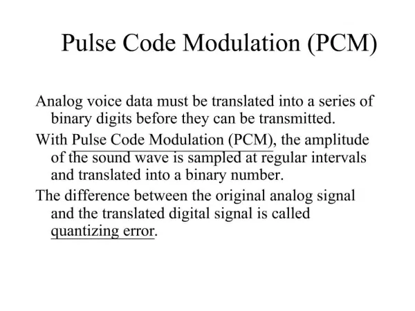
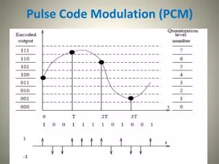
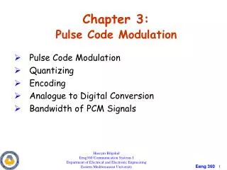
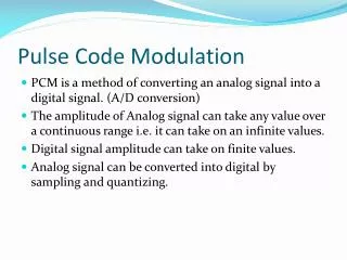
(1) Pulse Amplitude Modulation (PAM): • Analog Voice Signal Sampled converted to pulse stream • Pulse Amplitude: discrete analog signal, amplitude = • continuous analog signal • (2) Pulse Code Modulation(PCM): Quantize each Pulse into • Binary Form • - 8 bits used to quantize pulse range = 0..256 levels • - R = 8 bits * 8000Hz = 64kbpsper voice channel • - minimum unit of capacity available for lease
PAM signal PCM Signal sample clock Analog Voice Signal Digital Voice Signal Quantizer & Compander sampling circuit sample clock PAM signal PCM signal 10001010 10111010 125 us 8 bits
analog voltage range binary codeword 6..8 volts 4..6 volts 2..4 volts 0..2 volts 0..-2volts -2..-4 volts -4..-6 volts -6..-8volts 0 11 0 10 0 01 0 00 1 00 1 01 1 10 1 11 • q = quantization interval:signal (voltage) difference between • adjacent discrete signal levels • - accuracy determined by number of bits in signal: n bits 2n • levels • - signals within a level are represented by same binary codeword • - one bit may be used for signal polarity (+ or - ) e.g.n = 3 8 levels range 8volts (16 volts) interval q = 16/8 = 2 volts
V -V 0 11 0 10 0 01 0 00 1 00 1 01 1 10 1 11 q • Each codeword corresponds to nominal input voltage centered at q • actual input may differ by q/2 • quantization error, , actual signal amplitude – quantized signal • amplitude • quantization noise: random quantization error variance between • samples
+q/2 0 -q/2 - • actual amplitude • = quantization error
e.g. analog voltage range = 8 volts, n = 3 • 8 signal levels q = 2 volts • smaller amplitudes more sensitive to • ear is sensitive to noise on quiet, low amplitude speech signals
Compression and Expansion • continuous analog signal passed into compressor then into A/D • expander reverses the operation performed at output of D/A vi vo compressor expander Network D/A A/D • Practically non-linear PCM used to overcome quantization noise • 2 level digitization: segment level and quantization level • range of input signal amplitudes associated with each quantization • interval • input signal amplitude increases corresponding code words • represent larger signal range
At transmitter: analog voice non-linearly encoded into binary data • 1. compressor stage: analog input signal compressed • - encoded value depends on segment level • 2.ADC stage:compressed analog signal is digitized &linearly • quantized At receiver codewords converted to analog voice signal 1. DAC stage: compressed digital signal is linearly converted to analog signal 2. expander stage:analog output passed through expander – reverses compressor operation
e.g. Let Signal Range ± 30 volts and n = 5 bits • 32 total levels divided into • 1 polarity level • 2 segment levels • 2 quantum levels
‘+’ signal encoding • similar for ‘-’signal
segment levels 11 polarity bit 10 1 01 00 -16 -8 -4 -2 -V 2 4 8 16 V 0 quantum levels 00 01 10 11
PCM codecs (coder/decoder) • older codecs operated as above • newer codecs use 2 digital compression/expansion techniques • u-law: (N. America, Japan) • A-law: (ITU-T) • - similar in principal to companding-expansion • - conversion needed when using leased & switched circuits that • span continents • - necessary only for voice
Multiplexing (MUX) • Link Exchange Circuits: T1, T3, E1… • - carry multiple calls concurrently • - TDM Used: multiple digital signals assigned time slices • voice data: 8 bit sample @ 125us = 64kbps/ voice channel • control overhead: • (i) start of frame (frame synchronization) • (ii) call set-up (signaling)
slot 23 slot 23 … slot 1 slot 0 frame bit 125 us • slots 6,12: 1 signal bit, 7 data bits 56 kbps • slots 7-11, 13-24: 8 data bits 64 kbps • DS1 or T1 Links: • 24 voice channels grouped 1.536Mbps (North America) • (1 frame/125us 24 slots) = 192 bits/125 us • 192 bits + 1 framing bit = 193 bits/125 us 1.544Mbps • Signaling Info: carried in 1st bit of time slots 6-12 • - leaves 7 bits for data • Frame synchronization: bit (framing bit) at start of ‘frame 1’ • - toggles from 1,0 for consecutive frames
64Kbps links digital links slots 0 1 .. 23 23 …. 1,0 23 …. 1,0 193 bits clock=8 KHz synch bits DS1 or T1 Link
E1 Link: (ITU-T) • 30 voice channels at 64Kbps 1.920 Mbps • two additional slots for signaling and control • 32 (8/125us) = 2.048 Mbps • Signaling info: carried in time slot 16 • Frame synchronization: time slot 0 • - used for frame alignment • - allows receiver to interpret time slots in each frame on aligned • boundaries
Higher Aggregate Link Rates: MUX several groups (DSxx, Ey) • Higher order mux circuits: known as • - plesiochronous (nearly synchronous) • - asynchronous • PDH: (plesiochronous digital hierarchy) results in higher-order • mux rates • higher bit rate links require additional bits for framing & control Fractional T1, E1: Lower Bit Rates on T1, E1 systems
T1 = 2464Kbps links + control 64Kbps links T1 link 0 0 1 .. 23 clock=8 KHz 0 1 .. 23 T1 link 1 clock=8 KHz T3 link justification bit 0 1 .. 23 T3 = 28T1 links + control T1 link 27
T3 lines hub hub Public Carrier Network CSU/DSU CSU/DSU CSU/DSU CSU/DSU router router Leased Line Interconnection • channel service unit (CSU): • electrical barrier • keep alive signal • loopback test • data service unit (DSU) translate data format between entities • T1 uses TDM DSX frames for Data • LAN serial data frame format (e.g. ethernet) • physical connector to LAN