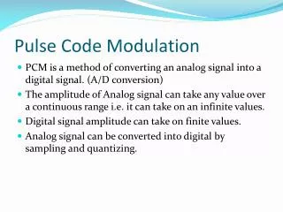
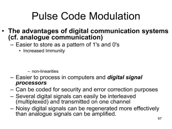
pulse code modulation
68. . . . . . . A brief aside about ADCs . 0000. 0110. 0111. 0011. 1100. 1001. 1011. . Numbers passed from ADC to computer to represent analogue voltage. ADCs are used to convert an analogue input voltage into a number that can be interpreted as a physical parameter by a computer.. 69. . . Sampling.

pulse code modulation
E N D
Presentation Transcript
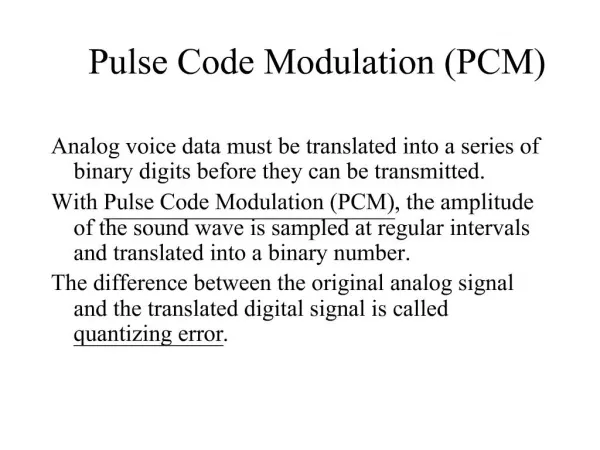
1. 67 Pulse Code Modulation The advantages of digital communication systems (cf. analogue communication)
Easier to store as a pattern of 1's and 0's
Increased Immunity
non-linearities
Easier to process in computers and digital signal processors
Can be coded for security and error correction purposes
Several digital signals can easily be interleaved (multiplexed) and transmitted on one channel
Noisy digital signals can be regenerated more effectively than analogue signals can be amplified.
2. 68
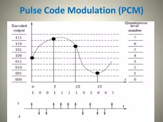
3. 69 Sampling The input signal is sampled prior to digitisation and an approximation to the input is reconstructed by the digital-to-analogue converter:
4. 70 Sampling an analogue signal Prior to digitisation, signals must be sampled
With a frequency fs=2B=1/T
ADC converts the height of each pulse into binary representation
Sampling involves the multiplication of the signal by a train of sampling pulses
5. 71 Sampling as multiplication by a sampling waveform: Multiplication = Amplitude modulation
Amplitude modulation produces sidebands�
6. 72 Sidebands produced by multiplication with a carrier
That is, amplitude modulation
7. 73 Sidebands at each harmonic of the sampling pulse
Digital-to-analogue conversion involves recovery of the baseband
How?
What is the minimum value of fs for which there is no overlap of the Harmonics with the baseband?
8. 74 If the sidebands do not overlap the signal can be recovered
9. 75 Practical sampling
the "Sample-and-hold" system:
This is Nyquist�s theorem
For a signal of bandwidth B Hz, the minimum sampling rate is 2B samples/s
10. 76 Effect of sampling rate
sampling at more than the Nyquist Rate
11. 77 Sampling at the Nyquist Rate
cannot build an ideal filter -
12. 78 Undersampling �
produces aliasing distortion!
13. 79 Aliasing-time domain
14. 80 The Anti-alias (Pre-sampling) filter
ensures that sampling obeys the Nyquist theorem
15. 81 Examples For the compact disc (Audio CD) the maximum signal frequency is 20 kHz and the sampling rate is 44.1 kHz.
The Nyquist Sampling Rate is 40 kHz
Hence the guard band is 4.1 kHz wide.
In the telephone system (see Section 5.8), the speech signal has a bandwidth up to 3.4 kHz and a sampling rate of 8 kHz,
The Nyquist Sampling Rate is 6.8 kHz
Hence the guard band is 1.2 kHz wide.
16. 82 Regeneration v amplification: Gain of amplifiers equals loss in transmission lines
SNR analog: S/kN
SNR digital: S/N
In practice finite S/N means there will be a low level of bit errors
Some accumulation of bit-error noise with repeaters, but much lower level than with analogue amplification
17. 83 A Pulse-Code Modulation communication system
"PCM"
18. 84 A digital communication system - "PCM" Anti-alias Filter*
Digitiser/Sample-and-Hold circuit*
Analogue-to-Digital Converter*
Coding-
Source coding for data compression,
Line coding for signalling efficiency
Error coding to reduce the effect of errors
Modulator
Physical Channel (with repeaters if necessary)*
Copper cables
Fibre Optic cables
Radio
Sonar
Recording medium
Demodulator
Decoder (Source-, Line- and Error-)
Digital-to-Analogue Converter*
Reconstruction Filter*
19. 85 Time-division Multiplexing "TDM" Allocate interleaved time-slots to each signal
Assemble the binary coded samples into Frames:
2-channel time-division multiplexing scheme:
20. 86 The 32-channel PCM Transmission system 30 speech signals plus two control channels for signalling and synchronising:
Signal bandwidth 3.4 kHz
Sampling rate 8 kHz
Hence frame length?
Sample size 8 bits/sample
Hence bit rate from each signal 64 kbit/s
32 channels
Hence each time slot 3.906 ?s
1/(8000*32)
Overall data rate 2.048 Mbit/s
8000*32*8
21. 87
22. 88 A number of frames can be time-division multiplexed together in a TDM heirachy.
4 frames of 32 channels
= 128 basic PCM channels,
Has data rate of 4 x 2.048 Mbit/s = 8.192 Mbit/s
8.448Mbit/s including extra signalling bits
4 x 128 = 512 channels
Has data rate = 4 x8.192 Mbit/s (+ signalling bits)
= 34.368 Mbit/s
etc
Up to a multiplex of 32768 channels with an overall data rate of 2.48832 Gbit/s.
23. 89
24. 90 Spectrum of a train of pulses: