Pulse Code Modulation
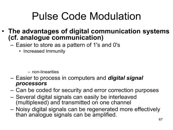
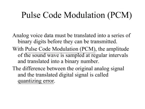
Pulse Code Modulation. PCM is a method of converting an analog signal into a digital signal. (A/D conversion) The amplitude of Analog signal can take any value over a continuous range i.e. it can take on an infinite values. Digital signal amplitude can take on finite values.

Pulse Code Modulation
E N D
Presentation Transcript
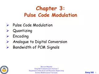
Pulse Code Modulation • PCM is a method of converting an analog signal into a digital signal. (A/D conversion) • The amplitude of Analog signal can take any value over a continuous range i.e. it can take on an infinite values. • Digital signal amplitude can take on finite values. • Analog signal can be converted into digital by sampling and quantizing.
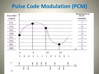
Cont. • The amplitude of analog signal m(t) lie in the range (-mp, mp) and is partitioned into L sub-intervals each of magnitude 2mp/L
Quantizing • Digital signals come from variety of sources e.g. computer • Some sources are analog but are converted into digital form by variety of techniques such as PCM and DM • For quantizing , we limit the amplitude of m(t) to a range(-mp, mp) as shown in the previous slides • This amplitude is uniformly divided into L subintervals and each interval is ,
Cont. • A sample value is approximated by the mid point of the interval • The quantized samples are coded and transmitted as binary pulses • At the receiver some pulses will be detected incorrectly • There are two types of errors • Quantization error • Pulse detection error
Cont. • In almost all practical schemes, the pulse detection error is very small compared to the quantization error and can be ignored • Now we analyze the quantization error
Cont. • The integral of the cross product terms is zero and we obtain, • Because the sampling rate is 2B, hence the total number of samples over the averaging interval is 2BT • This is called the mean of the quantization error
Cont. • The quantized levels are separated by 2mp/L • Since sample value is approximated by the midpoint of the subinterval in which the sample falls • The maximum quantization error is • The mean square quantizing error is
Non-uniform quantization • SNR is an indication of the quality of the received signal • Ideally we would like to have constant SNR • Unfortunately, the SNR is directly proportional to the signal power, which varies from talker to talker • The signal power can also vary because of the connecting circuits • SNR vary even for the same talker, when the person speaks softly • Smaller amplitudes pre-dominate in speech and larger amplitude much less frequent. • This means the SNR will be low most of the time
Cont. • The root of this difficulty is that the quantization steps are of uniform value • The quantization noise is directly proportional to the square of the step size. • The problem can be solved by using smaller steps for smaller amplitudes as shown in fig. on the next slide
Cont. • The same result can be obtained by first compressing a signal and then using uniform quantization • The input-output characteristics of compressor are shown in fig.
Cont. • The horizontal axis is normalized input signal and the vertical axis is the output signal y. • The compressor maps the input signal into larger increments • Hence the interval delta(m) contains large number of steps when m is small • The quantization noise is small for smaller input signal • Thus loud talker and stronger signals are penalized with higher noise steps in order to compensate the soft talker and weak signals
Compression Laws • There are two laws regarding compressions • (1) • This law is used in North America and Japan • (2) A-Law • This law is used in Europe and the rest of the word
Cont. • The compressed samples are restored to their original values at receiver by using an expander • The compressor and expander together are called compandor. • Compression of a signal increases its bandwidth but in PCM, we are not compressing the signal but its samples the number of samples does not change, therefore bandwidth does not rise • When meu-law compandor is used then output SNR is
Transmission BW and output SNR • For binary PCM, we assign distinct group of n binary digits to each of the L quantization levels • Each quantized level is encoded into n-bits • Minimum channel BW is • This is the theoretical minimum transmission bandwidth required to transmit the PCM signal
Example 6.2 • A signal m(t) band-limited to 3kHz is sampled at a rate 33.33% higher than Nyquist rate, a maximum acceptable error in the sample amplitude is 0.5% of the peak amplitude. The quantized samples are binary coded. Find the minimum channel BW required to transmit the coded signal. If 24 such channels are time-division multiplexed, determine the minimum transmission BW required to transmit the multiplexed signal
Comments on Logarithmic Units • Very small and very large values are expressed in logarithmic units
T1 carrier system • A schematic of T1-system is shown in fig.