Download
1 / 51
510 likes | 549 Views
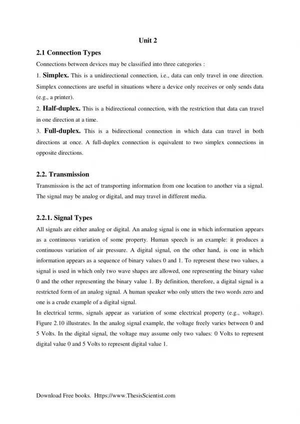
All signals are either analog or digital. An analog signal is one in which information appears as a continuous variation of some property. Human speech is an example: it produces a continuous variation of air pressure. A digital signal, on the other hand, is one in which information appears as a sequence of binary values 0 and 1. To represent these two values, a signal is used in which only two wave shapes are allowed, one representing the binary value 0 and the other representing the binary value 1. By definition, therefore, a digital signal is a restricted form of an analog signal. A human speaker who only utters the two words zero and one is a crude example of a digital signal.<br>In electrical terms, signals appear as variation of some electrical property (e.g., voltage). Figure 2.10 illustrates. In the analog signal example, the voltage freely varies between 0 and 5 Volts. In the digital signal, the voltage may assume only two values: 0 Volts to represent digital value 0 and 5 Volts to represent digital value 1.

E N D
Unit 2 2.1 Connection Types Connections between devices may be classified into three categories : 1. Simplex. This is a unidirectional connection, i.e., data can only travel in one direction. Simplex connections are useful in situations where a device only receives or only sends data (e.g., a printer). 2. Half-duplex. This is a bidirectional connection, with the restriction that data can travel in one direction at a time. 3. Full-duplex. This is a bidirectional connection in which data can travel in both directions at once. A full-duplex connection is equivalent to two simplex connections in opposite directions. 2.2. Transmission Transmission is the act of transporting information from one location to another via a signal. The signal may be analog or digital, and may travel in different media. 2.2.1. Signal Types All signals are either analog or digital. An analog signal is one in which information appears as a continuous variation of some property. Human speech is an example: it produces a continuous variation of air pressure. A digital signal, on the other hand, is one in which information appears as a sequence of binary values 0 and 1. To represent these two values, a signal is used in which only two wave shapes are allowed, one representing the binary value 0 and the other representing the binary value 1. By definition, therefore, a digital signal is a restricted form of an analog signal. A human speaker who only utters the two words zero and one is a crude example of a digital signal. In electrical terms, signals appear as variation of some electrical property (e.g., voltage). Figure 2.10 illustrates. In the analog signal example, the voltage freely varies between 0 and 5 Volts. In the digital signal, the voltage may assume only two values: 0 Volts to represent digital value 0 and 5 Volts to represent digital value 1. Download Free books. Https://www.ThesisScientist.com
Figure 2.10 Analog and digital signals. analog digital 5v 5v 0v 0v 1 0 1 1 time time Since digital computers play a central role in data communication, in nearly all cases, digital signals are used. Analog signals are used in cases of equipment which date back to before the advent of digital technology. Existing analog telephone networks are a good example of the latter. 2.2.2. Modulation Transmission of digital data over an analog line is achieved using a technique called modulation, where the digital bit stream is modulated over an analog carrier signal. A modem(modulator and demodulator) is a commonly used device which employs this technique. As illustrated in Figure 2.11, a modem converts the outgoing digital bit stream from a device into an analog signal and converts the incoming analog signal into a digital bit stream. Figure 2.11 Role of modems. modem modem Three basic types of modulation are possible (see Figure 2.12 for a visual comparison): Amplitude Modulation (AM).In AM, the carrier signal’s amplitude is changed 1. according to the modulating digital signal’s bit value. For example, two amplitude sizes (a small and a large one) may be used to, respectively, represent bit values 0 and 1. AM’s main weakness is its susceptibility to distortion. Frequency Modulation (FM).In FM, the carrier signal’s frequency is changed 2. according to the modulating digital signal’s bit value. For example, two frequency values (a low and a high one) may be used to, respectively, represent bit values 0 and 1. FM is more resistant to distortion than AM. Download Free books. Https://www.ThesisScientist.com
Phase Modulation (PM).In PM, the carrier signal’s phase is changed according 3. to the modulating digital signal’s bit value. A change in the carriersignal’s phase indicates a change in the modulating digital signal’s bit value from 0 to 1 or from 1 to 0. Figure 2.12 Three basic modulation methods. 1 0 1 0 Modulating digital signal (bit stream 1010) Carrier signal Amplitude Modulation (AM) Frequency Modulation (FM) Phase Modulation (PM) 2.2.3. Digitization Digitization is essentially the opposite of modulation. Whereas in modulation a digital signal is modulated over an analog signal for transmission, in digitization an analog signal is converted into digital format through a process of sampling. For example, the analog signal resulting from human speech can be sampled and converted into digital data, transmitted over digital lines, and converted back to analog signal at the other end. These two functions are performed by a device called codec (coder/decoder). Figure 2.13 illustrates the concept. Figure 2.13 Role of codecs. Download Free books. Https://www.ThesisScientist.com
codec codec It is worth noting that, unlike modulation (which is an exact process since the digital signal at the source and the digital signal received at the destination are identical), digitization is only an approximate process because of sampling. Figure 2.14 illustrates how an analog signal is sampled. The Physical Layer 23 value which is in turn represented by an integer in the range 0-255 so that it can be represented in one byte of data. This process (of representing a continuous value with a discrete value) is called quantization. The relatively small loss of information inherent in the process is called quantization error. The coding process generates the sample data from the analog signal. The decoding process regenerates an approximation of the original signal by fitting a smooth curve to the sampled points. The quality of the regenerated signal can be improved by increasing the sampling rate (i.e., reducing the sampling interval), but up to a limit dictated by the Nyquist’s theorem. This limit is exercised by a popular digitization technique called Pulse Code Modulation (PCM) which uses a sampling rate twice that of the original signal frequency. For example, a 4 kHz speech signal is sampled at a rate of 8000 samples per second. The main advantage of digitization is that, due to its resistance to distortion, it is much easier to reliably transmit a digital signal over a long distance than an analog signal. Figure 2.14 Sampling an analog signal. 255 127 0 miliseconds 5 10 15 20 2.2.4. Synchronization When two devices are about to communicate, the transmitter should somehow notify the receiver as to when to expect to receive data. This allows the receiver to prepare itself for receiving the data. Furthermore, such notifications should occur frequently enough so that Download Free books. Https://www.ThesisScientist.com
both devices maintain an agreement about the exact distribution of data over time. This process is called synchronization. There are two basic methods of synchronization: synchronous transmission and asynchronous transmission. In synchronous transmission, a clock signal is used as a common source of reference by both the transmitter and the receiver. By tying the data signal to the clock signal, either device can look at the clock signal to know where data bits may begin or end. The clock signal may be provided on a separate line, or be embedded in the data signal itself (see Figure 2.15). Because having a 24 Communication Networks Copyright © 2005 PragSoft separate clock line increases the costs, it is only used for covering very short distances (e.g., for connecting personal computers). Figure 2.15 Synchronous and asynchronous transmission methods. clock Synchronous with separate clock signal 01001011 data sync byte sync byte Synchronous with embedded clock signal ... byte byte byte byte byte byte stop bit start bit Asynchronous ... byte byte byte byte In asynchronous transmission, the beginning and end of each byte of data is marked by start and stop bits. This enables the receiver to work out the byte boundaries (see Figure 2.15). Because of its simplicity, asynchronous transmission is cheaper to implement and is therefore more widely used. 2.2.5. Transmission Media Digital data can be transmitted over many different types of media. Selecting a transmission medium is guided by comparing transmission requirements against the medium’s characteristics. Four important criteria influence the choice : Bandwidth. Bandwidth is the maximum frequency range that can be 1. practically supported by a medium. This is usually expressed in kilo Hz (kHz) or mega Hz (MHz). For example, analog transmission of human speech typically requires a bandwidth of 4 kHz. Also related, is the notion of data Download Free books. Https://www.ThesisScientist.com
rate, which denotes the maximum number of bits per second (bps) that can be transmitted. For example, a data rate of 10 mbps means that 10 million bits of data can be transmitted in each second. Because of their obvious relationship, the terms bandwidth and data rate are sometimes used interchangeably. Because of distortion factors, bandwidth and data rate are usually inversely proportional to the communication distance. Cost. Two types of cost are relevant: (i) the cost of installing the medium, 2. including the medium-specific equipment that may be needed, and (ii) the cost of running and maintaining the medium and its equipment. There is usually a need for tradeoff between cost, bandwidth, and distance. Reliability. Some media, by their physical nature, transmit data more reliably 3. than others. Low reliability translates into a higher number of errors, which needs to be balanced against the potential cost of recovering from the errors (e.g., retransmission, more complex hardware and software). Coverage. The physical characteristics of a medium dictate how long a signal 4. can travel in it before it is distorted beyond recognition. To cover larger areas, repeaters are needed to restore the signal, and this increases the costs. Transmission media may be classified into the following categories : Copper Wire. This is the oldest form of electronic transmission medium. Its use dates back to the development of telegraph in the 1800s and earliest telephone systems. Early installations used open wires, but these were superseded by twisted pairs, which consist of a pair of insulated and twisted wires (see Figure 2.16). Twisted pairs are superior because of reduced crosstalk.2 They are very effective for relatively short distances (a few hundred feet), but can be used for up to a few kilometers. A twisted pair has a bandwidth to distance ratio of about 1 MHz per kilometer. The performance of the twisted pair can be substantially improved by adding a metallic shield around the wires. Shielded wires are much more resistant to thermal noise and crosstalk effects. Twisted pairs used for long distance connections (e.g., telephone lines) are usually organized as a much larger cable containing numerous twisted pairs. Coaxial Cable. A coaxial cable consists of four concentric cylinders: an inner conductor, surrounded by an insulating cylinder, surrounded by an outer conductor, surrounded by a final protective cover. This combination is called a Download Free books. Https://www.ThesisScientist.com
coax (see Figure 2.16). Coaxial cables are superior to twisted pairs both in terms of bandwidth and communication distance, and can provide bandwidth to distance ratios in order of 10s of MHz per kilometer. Like twisted pairs, multiple coaxes are usually housed within one cable, which may also contain twisted pairs. Coaxial cables are extensively used in LANs and long distance telephone trunk lines. Optical Fiber. An optical fiber consists of two concentric cylinders: an inner core surrounded by a cladding. Both the core and the cladding are made of transparent plastic or glass material (see Figure 2.16). The core is used for guiding a light beam, whereas the cladding (which has a different refractive index) acts as a reflector to prevent the light from escaping from the core. Because optical fiber uses a light signal instead of electrons, it does not suffer from the various noise problems associated with electromagnetic signals. The signal is usually generated by a laser or Light Emitting Diode (LED). Optical fibers can provide bandwidth to distance ratios in order of 100s of MHz per kilometer. Like other cables, hundreds of optical fibers are usually housed within one cable. They are being increasingly used by telecommunication carriers for long distance 2 Crosstalk is the unwanted coupling effect between two or more signal paths, which causes signal distortion. digital trunk lines. Current trends promise that they will replace twisted pair residential loops in the near future. Radio. Radio signals have been used for a long time to transmit analog information. They are particularly attractive for long distance communication over difficult terrain or across the oceans, where the cost of installing cables can be too prohibitive. A minimum radio system consists of a transmitter and a receiver. It may operate at a variety of frequency bands, ranging from hundreds of Hz to hundreds of giga Hz (GHz). A huge range of transmission bandwidths are therefore possible. Microwave is by far the most widely used form of radio transmission. It operates in the GHz range with data rates in order of 100s of mbps per channel. Telecommunication carriers and TV stations are the primary users of microwave transmission. An important form of microwave system is a satellite system, which is essentially a microwave system plus a large repeater in the sky (see Figure 2.16). The signals transmitted by earth stations are received, amplified, and retransmitted to other Download Free books. Https://www.ThesisScientist.com
earth stations by the satellite. Like other microwave systems, the bandwidth is subdivided into channels of 10s of MHz each, providing data rates in order of 100s of mbps. Because of their high bandwidths, satellites are capable of supporting an enormous number and variety of channels, including TV, telephone, and data. The satellite itself, however, represents a major investment and typically has a limited lifetime (at most a few decades). Another increasingly-popular form of radio is cellular radio, which is currently being used by carriers for providing mobile telephone networks. These operate in the VHF band and subdivide their coverage area into conceptual cells, where each cell represents a limited area which is served by a low-power transmitter and receiver station. As the mobile user moves from one cell area to another, its communication is handed over from one station to another. Infra-red. Infra-red signals are suitable for transmission over relatively short distances (the signal is easily reflected by hard objects). The signal is generated and received using optical transceivers. Infra-red systems represent a cheap alternative to most other methods, because there is no cabling involved and the necessary equipment is relatively cheap. Data rates similar to those of twisted pairs are easily possible. However, applications are limited because of distance limitations (of about one kilometer). One recent use of infra-red has been for interfacing hand-held and portable computing devices to LANs (see Figure 2.16). Figure 2.16 Transmission media. Twisted Pair Satellite Repeater Coax Cover Inner Conductor Earth Station Earth Station Outer Conductor Insulation LAN Optical Fiber Infra-red Core Hand-held Computer Cladding Download Free books. Https://www.ThesisScientist.com
Figure 2.17 compares the characteristics of these media using the criteria mentioned earlier. It is important to note that the figures provided are approximate and continually improve as the technology moves forward. Figure 2.17 Relative comparison of transmission media. Medium Bandwidth Data Rates Cost Reliability Coverage Copper Cable 1 MHz 1-10 mbps Medium/km Low-Medium Kilometers Coaxial Cable 10s of MHz 10-100 mbps High/km Medium-High 10s of Kilometers Optical Fiber 100s of MHz 100s of mbps High/km Very High 10s of Kilometers Radio 100s of MHz 100s of mbps Very High Very High 1000s of Kilometers Infra-red 1 MHz 1-10 mbps Low Low-Medium Kilometer 2.3. Multiplexing Multiplexing is a technique which makes it possible to cram a number of logical channels (each capable of supporting an independent connection) into the same physical channel or line. The objective of multiplexing should be obvious: to reduce costs by better utilizing the capacity of a line. There are three basic multiplexing methods; these are separately described below. 2.3.1. Space Division Multiplexing (SDM) SDM is the simplest (and crudest) form of multiplexing. It involves grouping many separate wires into a common cable enclosure. A cable that has, for example, 50 twisted pairs inside it can support 50 channels. There is therefore a one-to-one correspondence between physical and logical channels (see Figure 2.18). SDM has the unique advantage of not requiring any multiplexing equipment. It is usually combined with other multiplexing techniques to better utilize the individual physical channels. Figure 2.18 Space division multiplexing. Download Free books. Https://www.ThesisScientist.com
cable enclosure 2.3.2. Frequency Division Multiplexing (FDM) In FDM, the frequency bandwidth of the line is divided into a number of partitions, each of which is used as a separate logical channel. Radio and TV broadcasting represent the oldest examples of FDM. To avoid neighboring channels from interfering with one another, the extreme ends of the channel frequencies are left unused to provide a gap. For example, a line that has a bandwidth of 30 kHz can be divided into 3 times 10 kHz channels, each of which consists of 8 kHz of bandwidth for data and two gaps of 1 kHz on either side. FDM requires special multiplexing/demultiplexing hardware (MUX) at either end of the line (see Figure 2.19). Figure 2.19 Frequency division multiplexing. 8kHz 30kHz 8kHz MUX MUX 30kHz 20kHz 10kHz 8kHz time time 2.3.3. Time Division Multiplexing (TDM) In TDM, each logical channel is allocated a time slot to transmit over a shared physical channel. For example, each logical channel may be given a 5 millisecond time slot to transmit, during which time it will have the entire bandwidth of the line to itself. Like FDM, TDM requires special multiplexing/demultiplexing hardware (MUX) at either end of the line (see Figure 2.20). Because the channels are spread across time, some means of initial synchronization is also needed. Basically, the receiving end needs to know which time slot belongs to the first channel when the connection is established, and can work everything else out from this reference point. Figure 2.20 Time division multiplexing. Download Free books. Https://www.ThesisScientist.com
time slot 101 011 001 101 001 MUX MUX 011 2.3.4. Concentration In multiplexing, a predetermined bandwidth is reserved for each of the logical channels, the sum of which for all the logical channels equates the bandwidth of the line. In practice, none of the logical channels is fully utilized at all times by the equipment attached to them. Consequently, if the bandwidth of each of the channels could be dynamically adjusted according to its traffic, then some cost savings could be achieved by using a lower capacity line. For example, a 9600 bps line could be used to serve 10 times 2400 bps channels, assuming that no more than 4 channels are used at any one time. This is made possible by a variation of TDM called concentration, where each channel is allocated a time slot only when it has data to transmit. 3.2.5. Flow Control The various stations in a network may operate at different speeds. One of the tasks of the data link layer is to ensure that slow devices are not swamped with data from fast devices. Flow control refers to the regulating of the rate of data flow from one 3 An octet consists of eight consecutive bits. In most systems this is the same as a byte, but there are also systems, where a byte has seven, or nine, or some other number of bits. In character-oriented protocols, flow control is usually based on two control characters: XON and XOFF. When the receiver senses that it can no longer accept incoming data, it sends an XOFF character to the transmitter, which causes the latter to stop transmitting. Once the receiver has consumed enough of the data in its receive buffer so that it can receive more, it sends an XON character to the transmitter, causing it to resume transmission. In bit-oriented protocols, flow control is handled through the use of ACK frames. Since the transmitter needs to keep a copy of its transmitted but yet unacknowledged frames in a buffer (in case they are corrupted and need to be Download Free books. Https://www.ThesisScientist.com
retransmitted), the size of the buffer imposes an upper limit on the number of such frames. When necessary, the receiver can use this fact to slow down the transmitter by withholding ACK frames. The protocol described in the next section uses exactly such a strategy. 3.3. Sliding Window Protocol Sliding window is a general protocol used with bit-oriented protocols. In this protocol, the transmitter maintains a variable, S, which denotes the sequence number of the next frame to be transmitted. Similarly, the receiver maintains a variable, R, which denotes the sequence number of the next frame it expects to receive. Both variables are restricted to a limited range of values (e.g., 0 through 7) by using modulo arithmetic (e.g., modulo 8). A window denotes a continuous subrange within the permitted range of values for the sequence numbers. For example, the ranges 0-3 and 6-1 both represent windows of size 3 (see Figure 3.30). Both the transmitter and the receiver have their own window: The transmitter window denotes the frames that have been transmitted but remain unacknowledged. This window can vary in size, from empty to the entire range. The transmitter must have enough buffer space to store the maximum possible number of unacknowledged frames. The receiver window denotes frames that are expected to be received. The receiver window size is fixed. A receiver window size of 1 means that frames must be received in transmission order. Larger window sizes allow the receiver to receive as many frames out of order. The receiver must have enough buffer space to store the maximum possible number of frames that can be received out of order. Download Free books. Https://www.ThesisScientist.com
The sliding window protocol operates as follows. When the transmitter sends a frame, it increments S (and the upper bound of its window). When the receiver receives a frame whose sequence number falls within its window, it increments R and sends an ACK to the transmitter. If the frame’s sequence number matches any position other than the lower bound of the window, it notes the fact that the corresponding frame has now been received. If the frame’s sequence number matches the lower bound of the window, the window is rotated clockwise by one position (or more positions if succeeding frames within the window have already been received). When the transmitter receives an ACK for a transmitted frame, it increments the lower bound of its window. Figure 3.31 illustrates the protocol for a sliding window of size 3, with the sequence number range 0-7. It should be now clear that flow control is straightforward in the sliding window protocol. If the receiver withholds ACK frames, the transmitter soon reaches its maximum window size and has to stop transmitting. Once it receives further ACK frames, it can reduce its window size and transmit more frames. Figure 3.31 Sliding window of size 3, with sequence numbers 0-7. Download Free books. Https://www.ThesisScientist.com
Transmitter Receiver Sl = 0 Sh = 0 Transmitter is idle Rl = 0 Rh = 3 Receiver is idle 7 0 7 0 6 1 6 1 2 2 5 5 4 3 4 3 Sl = 0 Sh = 1 Transmitter sends frame 1 Rl = 0 Rh = 3 Receiver is idle 7 0 7 0 6 1 6 1 2 2 5 5 4 3 4 3 Sl = 0 Sh = 2 Transmitter sends frame 2 Rl = 1 Rh = 4 Receiver receives frame 1 and returns ACK 7 0 7 0 6 1 6 1 2 2 5 5 4 4 3 3 Sl = 1 Sh = 2 Transmitter receives ACK for frame 1 Rl = 2 Rh = 5 Receiver receives frame 2 and returns ACK 7 0 7 0 6 1 6 1 2 2 5 5 4 4 3 3 Sl = 2 Sh = 2 Transmitter receives ACK for frame 2 Rl = 2 Rh = 5 Receiver is idle 7 0 7 0 6 1 6 1 5 2 2 5 4 3 4 3 3.4. Data Link Layer Standards The most commonly-used data link layer standards are a number of de facto standards established by major computer manufacturers (e.g., BSC by IBM and DDCMP by DEC) and others published by ISO, CCITT, and IEEE. Below we will look at two popular standards; one character-oriented and one bit-oriented. 3.4.1. BSC Binary Synchronous Control (BSC; also known as BISYNC) is a widely-used synchronous, character-oriented protocol devised by IBM in the 1960s for halfduplex communication. 4. Switching Methods Download Free books. Https://www.ThesisScientist.com
Switching is the generic method for establishing a path for point-to-point communication in a network. It involves the nodes in the network utilizing their direct communication lines to other nodes so that a path is established in a piecewise fashion (see Figure 4.). Each node has the capability to ‘switch’ to a neighboring node (i.e., a node to which it is directly connected) to further stretch the path until it is completed. Figure 4 A ‘switched’ path. One of the most important functions of the network layer is to employ the switching capability of the nodes in order to route messages across the network. There are two basic methods of switching: circuit switching and packet switching. These are separately discussed below. 4.1. Circuit Switching In circuit switching, two communicating stations are connected by a dedicated communication path which consists of intermediate nodes in the network and the links that connect these nodes. What is significant about circuit switching is that the communication path remains intact for the duration of the connection, engaging the nodes and the links involved in the path for that period. (However, these nodes and links are typically capable of supporting many channels, so only a portion of their capacity is taken away by the circuit.) Figure 4.1 shows a simple circuit switch which consists of a 3×3 matrix, capable of connecting any of its inlets (a, b, and c) to any of its outlets (d, e, and f). Each crosspoint appears as a circle. A hollow circle means that the crosspoint is off (i.e., the two crossing wires are not connected). A solid circles means that the crosspoint is on (i.e., the crossing wires are connected). The switch can support up to three simultaneous but independent connections. Figure 4.1 A simple circuit switch. a d b e c f 'on' crosspoint (connects b and f) 'off' crosspoint Download Free books. Https://www.ThesisScientist.com
Figure 4.1 shows a simple circuit-switched network built using the switch in Figure 4 2. When the two hosts shown in the figure initiate a connection, the network determines a path through the intermediate switches and establishes a circuit which is maintained for the duration of the connection. When the hosts disconnect, the network releases the circuit. Figure 4.2 Circuit switching. Circuit switching relies on dedicated equipment especially built for the purpose, and is the dominant form of switching in telephone networks. Its main advantage lies in its predictable behavior: because it uses a dedicated circuit, it can offer a constant throughput with no noticeable delay in transfer of data. This property is important in telephone networks, where even a short delay in voice traffic can have disruptive effects. Circuit switching’s main weakness is its inflexibility in dealing with computeroriented data. A circuit uses a fixed amount of bandwidth, regardless of whether it is used or not. In case of voice traffic, the bandwidth is usually well used because most of the time one of the two parties in a telephone conversation is speaking. However, computers behave differently; they tend to go through long silent periods followed by a sudden burst of data transfer. This leads to significant underutilization of circuit bandwidth. Another disadvantage of circuit switching is that the network is only capable of supporting a limited number of simultaneous circuits. When this limit is reached, the network blocks further attempts for connection until some of the existing circuits are released. Download Free books. Https://www.ThesisScientist.com
4.2.2. Packet Switching Packet switching was designed to address the shortcomings of circuit switching in dealing with data communication. Unlike circuit switching where communication is continuous along a dedicated circuit, in packet switching, communication is discrete in form of packets. Each packet is of a limited size and can hold up to a certain number of octets of user data. Larger messages are broken into smaller chunks so that they can be fitted into packets. In addition to user data, each packet carries additional information (in form of a header) to enable the network to route it to its final destination. A packet is handed over from node to node across the network. Each receiving node temporarily stores the packet, until the next node is ready to receive it, and then passes it onto the next node. This technique is called store-and-forward and overcomes one of the limitations of circuit switching. A packet-switched network has a much higher capacity for accepting further connections. Additional connections are usually not blocked but simply slow down existing connections, because they increase the overall number of packets in the network and hence increase the delivery time of each packet. Figure 4.3 shows a simple packet switch with six I/O channels (a through f). Each channel has an associated buffer which it uses to store packets in transit. The operation of the switch is controlled by a microprocessor. A packet received on any of the channels can be passed onto any of the other channels by the microprocessor moving it to the corresponding buffer. Figure 4.3 A simple packet switch. a buffer d b e c f microprocessor µP Two variations of packet switching exist: virtual circuit and datagram. Download Free books. Https://www.ThesisScientist.com
The virtual circuit method (also known as connection-oriented) is closer to circuit switching. Here a complete route is worked out prior to sending data packets. The route is established by sending a connection request packet along the route to the intended destination. This packet informs the intermediate nodes about the connection and the established route so that they will know how to route subsequent packets. The result is a circuit somewhat similar to those in circuit switching, Each packet carries a virtual circuit identifier which enables a node to determine to which virtual circuit it belongs and hence how it should be handled. (The virtual circuit identifier is essential because multiple virtual circuits may pass through the same node at the same time.) Because the route is fixed for the duration of the call, the nodes spend no effort in determining how to route packets. Figure 4.4 illustrates the virtual circuit method using the switch in Figure 4.4 When the two hosts initiate a connection, the network layer establishes a virtual circuit (denoted by shaded switches) which is maintained for the duration of the connection. When the hosts disconnect, the network layer releases the circuit. The packets in transit are displayed as dark boxes within the buffers. These packets travel only along the designated virtual circuit. Figure 4.4 Packet switching with virtual circuits. µP µP µP µP µP µP The datagram method (also known as connectionless) does not rely on a preestablished route, instead each packet is treated independently. Therefore, it is Download Free books. Https://www.ThesisScientist.com
possible for different packets to travel along different routes in the network to reach the same final destination. As a result, packets may arrive out of order, or even never arrive (due to node failure). It is up to the network user to deal with lost packets, and to rearrange packets to their original order. Because of the absence of a preestablished circuit, each packet must carry enough information in its header to enable the nodes to route it correctly. Figure 4.42 illustrates the datagram method. Note how the packets exercise different routes. Figure 4.42 Packet switching with datagrams. µP µP µP µP µP µP The advantage of the datagram approach is that because there is no circuit, congestion and faulty nodes can be avoided by choosing a different route. Also, connections can be established more quickly because of reduced overheads. This makes datagrams better suited than virtual circuits for brief connections. For example, database transactions in banking systems are of this nature, where each transaction involves only a few packets. The advantage of the virtual circuit approach is that because no separate routing is required for each packet, they are likely to reach their destination more quickly; this leads to improved throughput. Furthermore, packets always arrive in order. Virtual circuits are better suited to long connections that involve the transfer of large amounts of data (e.g., transfer of large files). Download Free books. Https://www.ThesisScientist.com
4.3.Packet Handling we will look at packets, their structure, and how they are handled by the network layer 4.3.1. Packet Structure The general structure of a virtual circuit packet is shown in Figures 4.43. The contents of the fields with darker shading vary according to the Packet Type, and may be altogether absent from some packets. Figure 4.43 General virtual circuit packet structure. Field Description Determines the internal format of the packet. Identifies the type of the packet. Identifies the virtual circuit for routing the packet. Parameters such as packet size, window size, etc. Parameters for the network service to which this packet belongs (see Section 4.1). Packet Format Packet Type Virtual Circuit ID Facilities Service Parameters User Data Actual network user data. Figure 4.44 shows the general structure of a datagram packet. Because packet headers may vary in length, the Header Length field is needed to indicate where User Data starts. Each packet is assigned a limited lifetime denoted by the Lifetime field. This is an integer quantity and is decreased in value by the nodes that handle the packet. When this value reaches zero, the packet is discarded. This is intended as a measure against congestion by packets that aimlessly circulate the network. Figure 4.44 General datagram packet structure. Download Free books. Https://www.ThesisScientist.com
Field Description Length of the packet header in bits or octets. Network address of the source end. Network address of the destination end. Packet lifetime indicator (to avoid packets living forever). Various options such as priority, security, etc. Header Length Source Address Destination Address Lifetime Options User Data Actual network user data. 4.3.2. Routing Routing is the task of selecting a path for the transport of packets across the network, and is one of the most important functions of the network layer. Routing is generally viewed as an optimization problem with the objective of choosing an optimal path according to certain criteria: Transmission cost (measured in terms of tied up network resources). Transmission delay (measured as the delay involved in delivering each packet). Throughput (measured as the total number of packets delivered per unit of time). The overall cost depends on all these three, and an optimal route is one that minimizes the overall cost. This can be represented by a weighted network, where an abstract cost figure is associated with each link, as illustrated in Figure 4.45. The cost of a route is the sum of the cost of its links. Figure 4.45 A weighted network. e 20 12 6 a d 5 g 7 b 8 4 11 11 c f There are three classes of routing algorithms: Flooding Static Routing Download Free books. Https://www.ThesisScientist.com
Dynamic Routing Of these, only dynamic routing makes any serious optimization attempts. In flooding, every possible path between the source and the destination station are exercised. Each node, upon receiving a packet, forwards copies of it to all its neighboring nodes (except the one from which it received the packet). Flooding is a highly robust technique since it offers the best chance of at least one packet copy reaching the destination. Its major disadvantage, however, is that it quickly congests the network. To avoid packets being indefinitely copied, each packet is assigned a limited lifetime which when expired will cause it to be destroyed (see Section 4.3.1). Because of its limitations, use of flooding is confined to specialized applications that require very high levels of robustness (e.g., military networks). Flooding is only suited to the datagram approach. In static routing, a fixed routing directory is used to guide the selection of a route which remains unchanged for the duration of the connection. The directory consists of a table which for each node pair (p,q) in the network suggests a partial path by nominating the first intermediate node, r, along the path. This should be interpreted as ‘to get from p to q, first go to r’. The path can then be continued by looking at the entry for the pair (r, q), etc., until q is reached. A sample route directory is shown in Figure 4.46. The route directory is tied to the network topology and remains unchanged unless the network topology changes. The route directory may be stored in a central location or distributed amongst the 62 Communication Networks nodes (each node requires its corresponding row only). The directory should remain accessible to network administrators for manual updates. 4.3.3. Congestion Control A network has a certain carrying capacity, denoted by the maximum number of packets that it can hold at any point in time. When this limit is approached, considerable delays are experienced in packet delivery, and the network is said to be congested. Congestion can occur in all types of networks. Uncontrolled congestion can lead to outright network failure. At the node level, congestion manifests itself as packet buffers that have approached their full capacity. This happens because the node is receiving more packets than it is passing on to the next nodes, which in turn are presumably unable to Download Free books. Https://www.ThesisScientist.com
receive more packets due to their buffers being full. When this situation occurs, the chances are that it will progressively get worse. The best way to deal with congestion is to avoid it. This is facilitated by putting in place measures that prevent buffer overflow. These measures include the following: Reducing the load on a node by disposing packets. As mentioned in earlier sections, packet disposal can be guided by a lifetime indicator which is eroded by the nodes that handle the packet. More blatant ways of disposing packets may also be employed. For example, a node that receives a packet for which it has almost no buffer space may destroy it immediately. Reducing the traffic destined for a heavily-utilized link. Nodes can monitor the traffic on their outgoing links and ask the source host to reduce the transmission rate when they feel that a link is approaching its capacity. The request can be put to the source host using a special packet. Imposing a limit on the total number of packets in the network. This approach requires some means of keeping a count of the packets in the network. Furthermore, the nodes will have to communicate to ensure that the count is kept up-to-date. Although, this approach ensures that the network cannot be overloaded with too many packets, it does not prevent an individual node from being overloaded. 4.3.4. Error Handling The extent to which the network layer attempts to deal with errors is largely dependent on the type of service being offered. If packets do not arrive due to being corrupted or lost, or if they arrive out of order, it is the responsibility of the network user to deal with these problems. The virtual circuit service, however, handles these problems transparently. The usual approach to dealing with corrupt or lost packets is to request retransmission. This issue was covered in earlier discussions. It is not uncommon for network protocols to have additional measures built into them to enable them to better deal with errors. For example, some protocols also use a CRC check on the packet header. To communicate the cause of detected errors, Download Free books. Https://www.ThesisScientist.com
some protocols use diagnostic packets. The subject area remains largely protocol dependent. 4.4.Internetworking It is an inevitable aspect of communication networks that because of business, organizational, political, and historical reasons, there exist many different types of networks throughout the world. More and more, it is becoming desirable, if not necessary, to interconnect these networks. Take, for example, the LANs operated by many universities around the world. These usually differ in many respects, but there has been a strong need to interconnect them so that the international academic and research community can freely exchange information. The problem of interconnecting a set of independent networks is called internetworking, and is illustrated by Figure 4.48. Each of the participating networks is referred to as a subnetwork (or subnet). The role of the Interworking Units (IWU) is to carry out protocol conversion between the subnets. IWUs are used for interconnecting networks that use the same architecture but employ different protocols. Because of this, they operate at the network layer and are commonly referred to as routers. Another type of protocol converter is a gateway. Unlike a router, it is used to interconnect networks of different architectures. Gateways operate at layers above the network layer and usually encompass all the layers. 4.5 A Simple Network Consider a small community of 100 families. The communication needs of this community can be served by one switch, to which every family (or subscriber) is directly connected (see Figure 4.5). The circuit which connects each subscriber (via a pair of wires) to the switch is called a subscriber loop. The switch itself is called a local exchange (local because the connection is direct). Figure 4.5 Single switch network. Download Free books. Https://www.ThesisScientist.com
subscriber loop 50 00 100-line Switch 49 99 A numbering scheme is used to uniquely identify each subscriber and to gather call-related information for billing purposes. In this case, a two-digit number would suffice (i.e., 00-99). When a subscriber dials the number of another subscriber, the switch follows a sequence of steps for establishing a communication path between the two subscribers. Provided the destination number is not engaged, a connection is guaranteed. Now suppose that there is a similar community with its own local exchange, and that we wish to provide phone access between the two communities. To do this, the two exchanges are connected using a set of interexchange lines called trunk lines (see Figure 4.6). In practice, it is unlikely that all of the subscribers in one community would want to simultaneously contact subscribers in the other community. If we establish that at most say six subscribers are likely to call the other community, then six trunk lines will be sufficient. The numbering scheme is expanded to take into account the above changes. Each subscriber is now allocated a three digit number. The first digit identifies the exchange (say 1 for the first community and 2 for the second community) and the next two digits identify a subscriber in that community as before. When a subscriber dials a number, the local exchange looks at the first digit of the number. If it matches its own number then it treats the remaining two digits as for a subscriber on the same exchange, and attempts to establish a direct connection between the two as before. If the first digit identifies the other exchange, Telephone Networks 123 inform the other switch of the call and passes to it the two remaining digits. The two switches then cooperate to establish a call between the two subscribers. Figure 4.6 A network with two switches. Download Free books. Https://www.ThesisScientist.com
Community 1 Community 2 1 2 200 100 Trunk Lines 100-line 100-line Switch Switch 199 299 If more than six subscribers attempt to simultaneously call subscribers on the other exchange, the seventh call and beyond will be blocked due to insufficient trunk lines. 4.6 Networks Topologies The simple network described in the previous section can be further expanded by adding exchanges. This may lead to two different types of topologies: mesh and star. A mesh topology is one in which each exchange is directly connected to every other exchange. In the star topology, each exchange is directly connected to a tandem exchange. A tandem exchange does not directly serve subscribers, but provides for interconnection between other switches. All of its lines, therefore, are trunk lines. The mesh configuration is suited to situations where there is heavy traffic between a set of local exchanges (e.g., in city centers with high business concentration). The star configuration is better suited to areas where there is not much traffic between the local exchanges (e.g., in suburbs). Most situations, however, are best served by a hybrid configuration which is primarily star-like but has additional trunk lines between exchanges where there is heavy traffic. The star topology can be taken a step further by interconnecting tandem exchanges from a number of star configurations to form a higher order star. Repeating this process results in a hierarchical network which consists of a number of levels. Figure 4.7 Basic network topologies. Download Free books. Https://www.ThesisScientist.com
Mesh Star Hybrid Local Exchange Tandem Exchange . It is made up of five classes of exchanges. A class 1 exchange represents a regional center and has the highest order in the hierarchy. A class 5 exchange represents an end office (local exchange) and has the lowest order in the hierarchy. Solid lines represent main trunk lines between exchanges. Dashed lines represent high usage trunk lines and can be established between any two exchanges, regardless of their levels in the hierarchy. Should the high usage trunks reach their maximum capacity, additional traffic is overflowed to the main trunks, from which further overflow is permitted. Because of this, the latter is also referred to as the final route. Figure 10.4 Hierarchical network. Download Free books. Https://www.ThesisScientist.com
Regional Centre 1 1 Trunks Sectional Centre 2 2 3 3 Primary Centre High Usage Trunks 4 4 Toll Centre 5 5 End Office Hierarchical networks have the advantage of requiring relatively simple switch designs. Their main disadvantage is that loss of connection at higher order trunks may severely disrupt the traffic. To reduce this risk, the highest order exchanges are usually interconnected in a mesh-like fashion. 4.7 Switching Systems Early telephone switches were electromechanical, many of which are still in use. They are so named because they use electromechanical relays to perform switching functions. The relays respond to the dial pulses from subscriber phones, and hence activate connections. Existing electromechanical switches are of two types: step-by-step and crossbar. A step-by-step switch uses step relays capable of assuming ten separate levels, to represent a decimal digit. Figure 4.7 A step-by-step switch. Download Free books. Https://www.ThesisScientist.com
incoming call to subscriber 16 1 Bank 1 ... . . . Bank 2 6 16 A crossbar switch consist of a matrix of crosspoints between rows of inlets and columns of outlets. Activating the relay of an inlet and the relay of an outlet causes the crosspoint at which they overlap to be activated and therefore result in a physical connection (see Figure 10.Error! Bookmark not defined.). Figure 4.7 A crossbar switch. Outlets Inlets An activated crosspoint Modern switches are microprocessor controlled and use digital switching technology. They are generally referred to as Stored Program Control (SPC) switches. Unlike electromechanical switches which are inherently hardwired and therefore inflexible, SPC switches achieve significant flexibility by using programmable logic. Because there are no moving parts involved, connections can be established orders of magnitude faster. Furthermore, the functions of the switch can be reconfigured through software (even remotely). Software control has facilitated the introduction of Download Free books. Https://www.ThesisScientist.com
many new service features which were previously beyond the scope of electromechanical switches. 4.8 Signaling Signaling refers to the exchange of control information between the components of a network (telephones, switches, etc.) in order to establish, manage, and disconnect calls. Four different types of signaling are used by telephone networks : Supervisory. This type of signaling provides the necessary control and status signals to establish calls, release calls, and make other service features possible. It includes the informing of exchanges about subscriber loop on- hook/off-hook conditions, and providing information about the status of calls. Address. This type of signaling conveys addressing information (subscriber number, area code, access code) between network components. Network Management. This type of signaling supports the management of network resources. It includes the handling of congestion and component failure situations, and the gathering and reporting of useful status information such as traffic conditions and operating anomalies. Audio-Visual. This type of signaling informs the calling subscriber about the status of a call, and alerts the called subscriber about a waiting call. Two categories of signaling are discussed below: subscriber signaling and interexchange signaling. 4.9 Subscriber Signaling Subscriber signaling refers to the signals exchanged between a subscriber and a local exchange via the subscriber’s loop. The sequence diagram in Figure 10.Error! Bookmark not defined. illustrates (a simplified version of) the signals exchanged for successfully establishing a call between two subscribers. Figure 4.9 Sample subscriber signaling scenario. Download Free books. Https://www.ThesisScientist.com
calling telephone called subscriber network subscriber OFF-HOOK DIAL-TONE DIAL-NUMBER RING RING-TONE OFF-HOOK STOP-RING-TONE STOP-RING conversation period ON-HOOK DISCONNECT ON-HOOK This process works as follows. We assume that initially both subscribers have their phones on-hook. The calling subscriber sends an off-hook signal to the local exchange by lifting the receiver. The switch responds by activating an audible dial tone over the subscriber loop, informing the subscriber that a number may be dialed now. The subscriber dials the other party’s number, and each dialed digit is signaled to the local exchange. This number is used as an address to route the call through the network and finally arrives at the local exchange of the called party. This local exchange applies a ringing signal to the called subscriber’s loop. At the same time, a confirmation is sent back to the calling subscriber’s local exchange, which in turn applies a ring tone to the calling subscriber’s local loop. This serves as an audible feedback that the number is dialed. When the called subscriber lifts the receiver, an off-hook signal is sent back to its local exchange. This causes the local exchange to stop the ringing, and is propagated back to the calling subscriber’s exchange which in turn stops the ring tone. The network connects the two parties and they may engage in a conversation. Either subscriber can terminate the call by pressing the hook switch. Download Free books. Https://www.ThesisScientist.com
This sends an on-hook signal to the local exchange, which in turn terminates the call and informs the other subscriber accordingly. Figure 4.9 Sample interexchange signaling scenario. calling telephone called exchange network exchange CONNECT CONNECT OFF-HOOK OFF-HOOK ON-HOOK ON-HOOK ADDRESS ADDRESS RING-TONE RING-TONE ANSWER ANSWER STOP-RING-TONE STOP-RING-TONE conversation period DISCONNECT DISCONNECT 4.10 Common Channel Signaling Thereare two general methods for conveying control signals between the components of a network: inchannel signaling and common channel signaling. With inchannel signalingInchannel the control signals occupy the same channel as the voice signal. It comes in two forms: in-band signaling uses audio tones for conveying its signals, out- of-band signaling reserves a narrow band within the voice band for conveying control signals. Inchannel signaling has the advantage of using the same trunk lines and equipment for carrying control signals as for voice signals. It has the disadvantage of being very limited both in speed and richness of signals that can be conveyed. Download Free books. Https://www.ThesisScientist.com
Common Channel Signaling (CCS) overcomes these limitations by using a channel separate from the voice channel for carrying the control signals. Because control signals have a lower bandwidth requirement than voice signals, the same 130 Communication Networks control channel can be used for carrying the control signals of multiple voice channels, hence the term common channel. Figure 4.10 Inchannel versus common channel signaling. Trunks Exchange Exchange (for voice and control signals) Switch Switch Inchannel Signaling Processor Processor Trunks Exchange Exchange (for voice signals only) Common Channel Switch Switch Signaling Common Channel (for control signals only) Processor Processor Because the two signal types are physically separated and independently handled, the overall network now consists of two networks: a voice network for carrying speech, and a distributed data network for carrying control signals. The relationship of these two networks results in two modes of operation: associated and nonassociated. In the associated mode the common channel is closely associated with the trunks so that the control signals for a call follow the same route as the voice signal. In the nonassociated mode the exchanges act as the Signaling Points (SP) as before, but additional Signal Transfer Points (STPs) are introduced to implement a signaling network of different topology to the voice network. As a result, the control signals no longer necessarily follow the same route as the voice signals. This produces two Download Free books. Https://www.ThesisScientist.com
independent networks with links at the switching points. Figure 10.Error! Bookmark not defined. compares the two modes. The nonassociated mode, while considerably more complex, offers all the flexibility of data networks for routing the control signals. For example, it is now possible to route call signaling information to a central point where information can be looked up in a database to obtain a service profile for handling the call. The Common Channel Interoffice Signaling (CCIS) system in North America which is based on the CCITT Signaling System Number 6 (SS6) is a living example of common channel signaling. CCIS supports both the associated and the nonassociated mode of operation. It uses packet switching for its control signaling. Each packet consists of a set of Signal Units (SUs) for conveying signaling information. Figure 10.10 CCS modes of operation. Exchange Associated Mode Trunks Common Channel SP (Exchange) Nonassociated Mode Trunks Common Channel STP The limited line speed of CCIS and SS6 (4.8 kbps and 2.4 kbps, respectively) and the limited size of the SUs has lead to the development of a replacement for SS6. This is discussed in the next section. 4.11 Signaling System Number 7 CCITT’s Signaling System Number 7 (SS7) was designed with the requirements of digital telephone networks in mind. As a common channel signaling standard, it is suitable for use with a wide range of circuit-switched digital networks. Like its predecessor, SS6, it uses packet switching, but is primarily designed to work with 64 Download Free books. Https://www.ThesisScientist.com
kbps digital channels of modern exchanges. However, it can also operate over analog channels of lower speeds, as well as digital channels of higher speeds. SS7 is a very large and complex system. It is the signaling system of choice for ISDN (discussed in the next chapter). The CCITT Q.700 series of recommendations which is comprised of numerous parts is entirely devoted to the definition of SS7. Since SS7 is a data network (similar to X.25, but designed for the specific application of signaling), it is useful to compare its protocol architecture to the OSI reference model. This is illustrated in Figure 10.Error! Bookmark not defined. Each level is separately discussed below. Figure 10.16 A corporate network. PBX London Trunks Leased Lines Central Office Exchange International Telephone Network PBX PBX New York Melbourne 4.11 Intelligent Networks SS7 opens the scope for user-defined procedures for the way calls are handled. This leads to the concept of Intelligent Networks (IN). A conceptual view of an intelligent network is shown in Figure 10.. Network access is facilitated through a set of Service Switching Points (SSPs). The signaling link between the switches is controlled through a set of Signaling Transfer Points (STPs). A Service Control Point (SCP) is in charge of dictating how calls should be handled and routed. For its operation, the SCP uses a service database which contains service profile definitions provided by the customer. Service profiles use a number of network-provided parameters (e.g., time and date of the call, origin of the call, network-related conditions) to determine how to handle calls. An Support Download Free books. Https://www.ThesisScientist.com
Management System (SMS) provides network management and customer control capabilities. Figure 10.17 An intelligent network. SMS STP SSP SCP STP STP SSP SSP IN applications include: Call Management Services (CMS), Customer Local Area Signaling Service (CLASS), Personal Communications Service (PCS), Centrex, Automatic Calling Card Service (ACCS), and basic and enhanced 800 service. The 800 (or 008) service is available in many countries.: Telephone Networks 139 customer is an organization with numerous outlets throughout the country (e.g., a fastfood chain). The service is characterized by a single number with the 800 prefix which, when dialed from anywhere in the country, is redirected to the SCP for handling. A typical service profile would use the origin of the call to direct it to the nearest outlet. 5. Integrated Services Digital Network Current trends in telecommunication are toward integration of voice and data services. So far these services have been available separately, requiring separate subscription, communication links, and equipment. It has long been acknowledged that the integration of these services will result in significant flexibility and cost benefits to both service users and service providers. The Integrated Service Digital Network (ISDN) is a major attempt to realize these objectives. The three most important ingredients of ISDN have already been discussed in earlier chapters: circuit switching, packet switching, and common channel signaling (SS7). This chapter looks at the rest of the ISDN technology. We will start with some Download Free books. Https://www.ThesisScientist.com
basic ISDN concepts, including its channels, reference points, functional groupings, and services. We will then describe the ISDN protocol architecture in relation to the OSI model, and discuss various ISDN standards. Finally, we will examine the potential future of ISDN within the context of global communication networks. 5.1. Basic Concepts ISDN provides a fully integrated digital network for voice and data communication. It supports both circuit and packet switching. Figure 5 illustrates the overall arrangement of a typical ISDN network, which brings together a mix of old and new technologies and devices. Each ISDN switch consists of an exchange termination part, which performs the necessary circuit switching functions, and a packet handler, which performs the necessary packet switching functions. The packet handlers implement X.25 and are connected to a public packet switched network via X.75. The exchange terminations are interconnected via tandem exchanges. STPs and SCPs provide network intelligence, and were described in the previous chapter. Subscriber access is provided via a network termination and/or terminal adapter (NT/TA). This provides the connectivity for a variety of user devices, including ISDN phones, Plain Old Telephone Sets (POTS), LANs, PBXs, and X.25 terminals. Figure 5 ISDN network overview. Download Free books. Https://www.ThesisScientist.com
To other ISDN exchanges Tandem Exchange To other ISDN exchanges STP SCP ISDN Switch ISDN Switch Exchange Termination Exchange Termination Packet Handler X.75 Public Packet Switched Network X.75 Packet Handler U ISDN Phone PBX POTS NT/TA LAN X.25 Access . ISDN Channels Subscriber access to ISDN is via digital channels, of which there are three types : B channels are used for carrying user data (digitized voice or computer generated data) at 64 kbps. This data rate is more than necessary in many situations (e.g., compressed digitized voice can be transmitted using less bandwidth). Consequently, a B channel is sometimes subdivided into smaller sub channel. Whether there is a subdivision or not, the network treats the whole thing as one channel. All sub channels therefore are between the same two endpoints and follow the same route. D channels are primarily used for common channel signaling purposes. They are typically associated with B channels and carry the control signals for B channel calls. D channels are also used for packet-switched data communication. A D channel may operate at 16 or 64 kbps. H channels are used in a high-speed trunk capacity. They are suitable for applications that require higher than 64 kbps data rates. Multi-media applications (e.g., audio, video, and graphics multiplexed over the same Download Free books. Https://www.ThesisScientist.com
channel) are examples. H channels are divided into three categories depending on their speed: H0 operates at 384 kbps (= 6 B channels) H11 operates at 1536 kbps (= 23 B channels) H12 operates at 1920 kbps (= 30 B channels) Only D channels can be used for carrying signaling information. B and H channels can only be used for carrying user data. In practice, channels are offered to users in a packaged form. Two such packages have been defined: basic access and primary access. The Basic Rate Access (BRA) package (also called 2B+D) is primarily intended for residential subscribers and consists of the following: Two B channels One 16 kbps D channel Overhead of 48 kbps for framing, synchronization, etc. This produces a total bit rate of 192 kbps. The channels may be used for a variety of purposes. For example, the two B channels can be used for two independent voice services, or one of them can be used for voice and the other for a data service such as fax, teletex, or remote LAN access. Modest data communication requirements (e.g., remote banking transactions) may be met by the D channel alone. Other permitted combinations for basic access are: B+D or just D. The Primary Rate Access (PRA) package is aimed at business users with greater bandwidth requirements. Primary access comes in two configurations : At a bit rate of 1.544 mbps (North America and Japan) and consisting of : 23 B channels One 64 kbps D channel Overhead of 8 kbps At a bit rate of 2.048 mbps (Europe) and consisting of : 30 B channels One 64 kbps D channel Overhead of 64 kbps As with the basic access, lower configurations are also possible, depending on requirements. Primary access can also support H channels. 5.1.2. ISDN Services Download Free books. Https://www.ThesisScientist.com
ISDN provides three types of services : Bearer services Teleservices Supplementary services Tele and supplementary services represent the type of features and functions which are visible to end-users, while bearer services represent the parts of the network which remain hidden from end-users. Bearer services facilitate the real-time communication of digital information between end-users. These services mainly relate to network functions and account for OSI layers 1-3. An example of a bearer services is the 64 kbps, 8 kHz structured, speech service. This service uses a data rate of 64 kbps together with 8 kHz timing information (which structures the data into octet intervals) for transmitting a Pulse Code Modulated (PCM) speech signal. The fact that the signal represents speech is known to the network, allowing it to employ transformations which may not preserve bit integrity but will result in good quality audio reproduction. By contrast, the 64 kbps, 8 kHz Structured, Unrestricted service makes no assumptions about the signal’s data content and is a general purpose service. There are also a number of other unrestricted services, offering successively higher bandwidths (e.g., 384, 1536, and 1920 kbps, 8 kHz Structured, Unrestricted services). In addition to the above circuit-switched bearer services, there are a number of packet-switched bearer services. For example, the User Signaling service is a packet- switched bearer service suitable for exchanging signaling information between end- users and is defined by recommendation I.451, which we will examine later in this chapter. Another example is the Connectionless on a D Channel service which provides a datagram service on a D channel and is suitable for control-oriented or transaction-oriented applications. Teleservices provide a set of higher-level functions on top of bearer services. These services account for OSI layers 4-7. Examples of teleservices are : Telephony services which provide speech communication over a B channel with control signaling over the D channel. Facsimile services which facilitate the communication of bitmap images over a B channel with control signaling over the D channel. Download Free books. Https://www.ThesisScientist.com
Teletex services which facilitate the interchange and communication of textual as well as formatted documents over a B channel with control signaling over the D channel. Supplementary services enhance bearer and teleservices in an independent fashion. Examples of supplementary services are : The Centrex service emulates a private network and provides specialized features to a set of subscribers. The Call Transfer service allows a user to transfer an active call to a third- party. The Call Waiting service allows a user already engaged in a call to be informed of another incoming call. The Calling Line ID service provides the calling party’s address information to the called party. Although these services all appear geared toward circuit-switched telephone calls, they are equally applicable to packet-switched data calls. Broadband ISDN and ATM 6. This chapter describes Broadband ISDN (B-ISDN) and the transfer mode designed for its implementation: Asynchronous Transfer Mode (ATM). ATM provides a means for fast switching and transmission at data rates required by B-ISDN services. It relies on the division of information into small fixed-size packets, called cells, and their demand-based transmission over optical fiber – hence the term asynchronous. We will first discribe some of the basic concepts underlying ATM, including its protocol architecture, and then discuss each of its layers in turn. 7.1. Broadband ISDN Increasing market demand for data rates substantially greater than those supported by ISDN has lead to the notion of Broadband ISDN (B-ISDN). By relying on optical fiber transmission systems, B-ISDN opens the door to a whole range of new applications (e.g., high quality digital audio, real-time video, pay TV, video phone, high speed LAN connection) with emphasis on interactivity and high speed transfer services. Download Free books. Https://www.ThesisScientist.com
B-ISDN is developed as an evolution of ISDN and hence follows the same principles. This section provides an overview of B-ISDN, its services, and its protocol architecture. 7.1.1. B-ISDN Services B-ISDN services are clasified into interactive and distribution services. Interactive services involve the bidirectional flow of user information between two subscribers or between a subscriber and a service provider. Interactive services are divided into three subcategories : Conversational services involve real-time exchange of information such as sound, video, data, or entire documents. Typical examples include: videotelephony, video-conference, and high speed data transfer. Video- telephony is like the normal voice telephony service but also includes video capture, transmission, and display capabilities. Video-conference provides voice and video communication between two conference rooms or between a number of individuals. Messaging services involve non-real-time exchange of information between subscribers in a store-and-forward fashion. Examples include: video mail and document mail. Video mail supports the exchange and storage of moving video images and sound as messages. Document mail allows documents of different types and formats to be exhanged and stored. Retrieval services provide subscribers with retrieval access to centrally-stored public information. Examples include: broadband videotex (retrieval of video images/sequences with sound, text, and graphics), video retrieval (subscriber access to video libraries of movies), and retrieval of high-resolution images and documents from various archives and information centres. Distribution services involve the unidirectional flow of user information from a service provider to a subcriber. Distribution services are divided into two subcategories : Distribution services without user presentation control involve the central broadcast of information to a large number of subscribers, where subscribers have no control over the presentation of information. Examples include: broadcast of TV programmes, electronic newspapers, and electronic publishing. Download Free books. Https://www.ThesisScientist.com
Distribution services with user presentation control are the same as the previous category except that here the information is offered as cyclicallyrepeated frames, thereby enabling the subscriber to control the start and the order of the presentation of frames. Examples include: electronic newspaper and tele-advertising. Figure 7.1 summarizes the B-ISDN services. Figure 12.136 Summary of B-ISDN services. Category Interactive Subcategory Conversational Type of Information Moving picture and sound Example Broadband video-telephony Broadband video-conference Video-surveillance Multiple sound prog. signal High speed data transfer High volume file transfer High speed teleaction High speed telefax High resolution image comm. Document communication Video mail Document mail Broadband videotex Video/Image retrieval Document/Data retrieval Data distribution Electronic newspaper Video signal distribution Sound Data Document Messaging Moving picture+sound Document Text, data, graphics, still images, moving pictures Data Text, graphics, images moving pictures+sound Video Text, graphics, sound, images Retrieval Distribution Without user presentation control TV programme distribution Electronic newspaper Tele-advertising With user presentation control 7.1.2. B-ISDN User-Network Interface Download Free books. Https://www.ThesisScientist.com
In addition to the narrowband channels defined for ISDN, B-ISDN supports the following three User-Network Interfaces (UNIs) : Symmetric full-duplex 155.52 Mbps. This interface provides the basis for interactive services. This will therefore be the most common interface offered. It is commonly referred to as the 150 Mbps interface. The effective payload of this interface is 149.76 Mbps. Symmetric full-duplex 622.08 Mbps. This interface is suitable for situations which involve very high traffic volumes. It is commonly referred to as the 600 Mbps interface. The effective payload of this interface is 599.04 Mbps or 600.768 Mbps, depending on how it is structured. Asymmetric full-duplex 622.08/155.52 Mbps. This is a hybrid interface which combines the earlier two. It uses bit rates of 622.08 in the network-to- subscriber direction and 155.52 Mbps in the subscriber-to-network direction. It is suitable for situations where the traffic volume in the network-to- subscriber direction is much higher than in the opposite direction. The functional groupings and reference points for B-ISDN UNI closely follow those of the narrowband, as illustrated by Figure 12.137. Their role remains identical to those of narrowband ISDN. To highlight the broadband nature of the functional groupings and reference points, the letter ‘B’ is added (e.g., B-TE1). The R reference point is an exception because it may or may not have broadband capabilities. Accordingly, it may support a B-TE2 or TE2. Figure 7.1.2 B-ISDN functional groupings and reference points. Functional groupings B-TE1 T B S B R B-ISDN Network B-NT1 B-NT2 B-TA B-TE2 or TE2 Reference points 7.3. B-ISDN Protocol Architecture Figure 7.3 shows the reference model for the B-ISDN protocol architecture. The architecture is partitioned by three planes. The User Plane facilitates the transfer of Download Free books. Https://www.ThesisScientist.com
user information and associated control signals. The Control Plane is responsible for connection control functions such as call setup and release. The Management Plane is responsible for management functions relating to the system as a whole and coordination between the planes (Plane Management), and for management functions related to resources and parameters residing in its protocol entities (Layer Management). Figure 7.3 B-ISDN protocol architecture reference model. Management Plane Control Plane User Plane Higher layers Higher layers ATM Adaptation Layer Plane Management ATM Layer Layer Management Physical Layer The Physical Layer is responsible for the physical transmission of ATM cells. To achieve some degree of physical medium independency, this layer is divided into two sublayers. The Physical Medium Sublayer covers the medium-dependent aspects of the physical layer and provides bit transmission and bit timing functions. The Transmission Convergence Sublayer is independent of the physical medium and provides five functions : Generation and recovery of transmission frames Transmission frame adaptation which involves the packing of cells into transmission frames and their extraction upon arrival. Cell delineation to enable the receiving-end identify the boundaries of cells whose information fields have been scrambled prior to transmission and are descrambled by the receiver. HEC sequence generation by the transmitter, and verification by the receiver. Cell rate decoupling through insertion of idle cells by the transmitter in order to adapt the cell rate to the playload capacity, and their removal by the receiver. Download Free books. Https://www.ThesisScientist.com
The ATM Layer is responsible for the transfer of cells across the network and is independent of the physical medium. It provides four functions : Cell multiplexing by the transmitter in order to support multiple logical channels, and their demultiplexing by the receiver. Virtual path and virtual channel identifier translation (explained in the next section). Cell header generation by the transmitter, and its extraction by the receiver. Generic flow control for the control of traffic in a customer network by placing flow control information in cell headers. The ATM Adaptation Layer (AAL) packages information from higher layers into ATM cells to be transported by the ATM layer at the transmitter end, and extracts information from ATM cells for passing to higher layers at the receiver end. It consists of two sublayers. The Segmentation and Reassembly Sublayer handles the segmentation of information from higher layers into smaller units so that they can be transported by ATM cells, and their subsequent reassembly upon arrival. The Convergence Sublayer specifies the services that AAL provides to higher layers and is service-dependent. The physical and the ATM layer provide the same functions for the user and the control plane. The ATM adaptation and higher layers, however, may provide different functions for these two planes. 7.4 Asynchronous Transfer Mode The recommended switching technology for B-ISDN is the Asynchronous Transfer Mode (ATM). Given the high reliability of optical fiber for transmission of digital information, the significant error control overheads involved in earlier protocols (such as X.25) become very questionable. Like frame relay, ATM takes advantage of this increased reliability to improve network performance by providing a highly streamlined protocol stack. ATM uses two methods to achieve this. First, it transmit all its information in fixed-size small packets, called cells, hence simplifying the processes of packaging and unpackaging user information. Second, unlike X.25 which requires error control and flow control functions to be performed in a link-by-link fashion, it only requires end-to-end support of these functions. Download Free books. Https://www.ThesisScientist.com
7.5 Channels and Paths Figure 7.5 illustrates the layered structure of B-ISDN. The higher layer functions are application-dependent and beyond the scope of this chapter. The 166 Communication Networks ATM transport network is divided into two layers, both of which are hierarchically organized. Figure 7.5 Layered structure of B-ISDN. B-ISDN Higher Layer Functions ATM Transport Network ATM Layer Transport Functions Virtual Channel Level Virtual Path Level Physical Layer Transport Functions Transmission Path Level Digital Section Level Regenerator Section Level The ATM layer transport functions are divided into virtual channel level and virtual path level. A Virtual Channel (VC) denotes the transport of ATM cells which have the same unique identifier, called the Virtual Channel Identifier (VCI). This identifier is encoded in the cell header. A virtual channel represents the basic means of communication between two end-points, and is analogous to an X.25 virtual circuit. A Virtual Path (VP) denotes the transport of ATM cells belonging to virtual channels which share a common identifier, called the Virtual Path Identifier (VPI), which is also encoded in the cell header. A virtual path, in other words, is a grouping of virtual channels which connect the same end-points. This two layer approach Download Free books. Https://www.ThesisScientist.com
results in improved network performance. Once a virtual path is setup, the addition/removal of virtual channels is straightforward. The physical layer transport functions are divided into three levels of functionality. The transmission path connects network elements that assemble and disassemble the transmission system payload. This payload may contain user or signalling information to which transmission overheads are added. The digital section connects network elements (such as switches) that assemble and disassemble continuous bit/byte streams. The regenarator section is simply a portion of a digital section which connects two adjacent repeaters along a transmission path which is otherwise too long to sustain the signal. Figure 7.5 illustrates the relationship between virtual channel, virtual path, and transmission path. Figure 7.5 Virtual channel, virtual path, and transmission path. VC VP VC VP Transmission Path VC VP VC VP VC VP VC VP Two types of switching are possible: VP switching and VC switching. A VP switch connects a set of incoming VP terminations to a set of outgoing VP terminations. The mapped VPs will have different VPIs, but the VCI will remain unchanged. A VC switch, on the other hand, connects a set of incoming VC terminations to a set of outgoing VC termination. VCIs are not preserved. Because VCs are embedded in VPs, VC switching also involves VP switching. 7.6 . ATM Cells An ATM cell consists of 53 consecutive octets, of which 48 octents are used to represent user information and the remaining 5 octets form a header for the private use of the ATM protocols Download Free books. Https://www.ThesisScientist.com
Figure 7.6 ATM cell structure. Field Description GFC VPI VCI Generic Flow Control field for end-to-end flow control Virtual Path Identifier for routing Virtual Channel Identifier for routing Header (5 octets) PT CLP HEC Payload Type for the information field Cell Loss Priority for discarding of cells in congestions Header Error Control code Body Information User information or inband signaling information (48 octets) The GFC field is intended for the user-network interface only. (It does not appear in the header format of cells used for the internal operation of the network. Its 4 bits are instead used by the VPI.) It can be used by applications to provide endto- end flow control. The VPI and VCI fields collectively support the routing of a cell by the network. The PT field denotes the type of information stored in the information field. ATM Layer 7.7 The ATM layer uses a cell as its basic unit of communication. Unlike the physical layer, at the ATM layer only the logical structure of a cell is of interest. Cells which are for the use of the physical layer only are distinguished by having the VPI and VCI set to 0, and the least significant bit of the fourth octet in the cell header set to 1. Except for the HEC field which is not used by the ATM layer, the remaining ATM cell fields are separately discussed below. 7.9 Virtual Path Identifier Download Free books. Https://www.ThesisScientist.com
The VPI field is 8 bits wide for the UNI and 12 bits wide for the Network-Network Interface (NNI). It is used to distinguish between VP links multiplexed into the same physical connection. All cells belonging to the same VP are assigned the same VPI. As explained earlier, certain cells may be assigned predetermined VPIs. A VPI is mapped at a VP link termination, such as a switch. A Virtual Path Connection (VPC) is a concatenation of VP links, along which the VCIs may be mapped link-by-link. A VPC preserves the cell sequence for each of the channels it contains. 7.10 Virtual Channel Identifier The VCI field is 16 bits wide and is used to distinguish between VCs sharing the same VP connection. Combined with the VPI, it provides a complete routing identifier. All cells belonging to the same virtual channel are assigned the same VCI. Predetrmined VCIs are used for cells serving special purposes. A VCI is mapped at a VC link termination, such as a switch. A Virtual Channel Connection (VCC) is a concatenation of VC links. It preserves the cell sequence. At the UNI, a VCC may be established/released using different methods: through user-network signaling, through meta signaling, or as a result of subscription (without signaling). 7.11 Payload Type This field is 2 bits wide and denotes the type of the information stored in the cell. A PT value of 00 is used for cells carrying user information. Other values can be used for representing control information to provide an inband signaling capability. 7.12 Cell Loss Priority This is a single-bit field and hence may assume a value of 0 or 1. When set to 0, it indicates to the network that this cell should not be discarded as long as possible. In a congestion situation, therefore, the network will give preference to the discarding of cells with a CLP of 1. This field may be set by the user or the network. 7.13 ATM Adaptation Layer The AAL supports the use of non-ATM protocols (e.g., LAP-D) for the transfer of information. It does so by mapping information from other protocols (e.g., LAP-D frames) into ATM cells before transmission and their reassembly upon arrival. Four classes of AAL services have been identified on the basis of the timing relation between source and destination, the bit rate, and the connection mode. These Download Free books. Https://www.ThesisScientist.com