Download
1 / 24
250 likes | 282 Views
Learn about computer networks, network types, models of networking, and transmission modes. Explore LAN, WAN, protocols, and the client-server model. Gain insights into centralized, distributed, and cooperative computing models.

E N D
5.1 COMPUTER NETWORKSUnit 1: Networks Basics By: Dr. SHOBHA RANI Lecturer in Computer Engg.
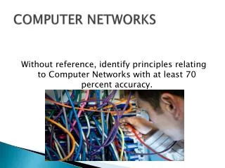
2. Computer Network : • A system containing any combination of computers, computer terminals, printers, audio or visual display devices, or telephones interconnected by telecommunication equipment or cables: use tdo transmit or receive information.
The Network Diagram(Click on the Words Below and Learn More About Each Component) Wired Network PC Firewall The Internet Fiber Optic Network Cable Router Switch Server Other LANS Wireless Network
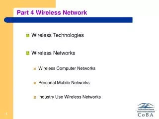
4. Network Types • Computer networks vary in shape and size • depending on usage. • - WAN • - LAN • - Peer to Peer
WAN PEER TO PEER LAN
Wide Area Network: • . Wide Area Network exist over a large area • Data travels through telephone or cable lines • Usually requires a Modem • The world’s largest Wide Area Network in the Internet
Local Area Network : • A Local Area Network spans a relatively small area • LAN are usually confined to one building or a group of buildings • Data travel between network devices via network cables. • The most common type of Local Area Network is called Ethernet
Peer to Peer Network: • Usually very small networks • Each workstation has equivalent capabilities and responsibilities • Does not require a switch or a hub. • These types of networks do not perform well under heavy data loads.
Models of Networking Centralised computing Peer-to-peer networks Client-server networks
Networking models: The type of network most widely implemented to day is based on the principle of having one or more file servers at the heart of the network. This kind of network is often referred to as a server-based or client-server network. There are however other models for implementing networks. The three principal ways of connecting computers together to share or use network resources are:
Network computing is a generic term in computing which refers to computers or nodes working together over a network. It may also mean: Cloud computing, a kind of Internet-based computing that provides shared processing resources and data to devices on demand Distributed computing Virtual Network Computing
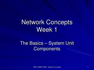
6. Models of Network Computing • After you have the necessary prerequisites for network communication, a structure must be put in place that organizes the way communication and sharing occur. Three methods of organization, or models, are generally recognized. The three models for network computing are as follows:1. Centralized computing • 2. Distributed computing • 3. Collaborative or cooperative computing • These three models are the basis for the various types of computer networks you learn about in this book. The following sections discuss the three models for network computing.
Computer Network Computer network is a number of computers (also Known as Nodes) connected by some communication lines. Uses of Computer Network: Exchange of information between them Interconnected small computers in place of large computers For direct communication e g: voice , video. 4. Modes of Communication Point to point Broadcasting Multicasting it is between the point to point and broadcasting Dedicated (Simplex, half duplex, full duplex). Shared (Multiplexing). Dedicated (Channel level- one way) Shared (Multiple access) shared between multiple access and some protocols are used that how they are using. Communication to the specified group but not to others. 5. Transmission Modes Simplex One direction ○ e.g. Television Half duplex Either direction, but only one way at a time ○ e.g. police radio Full duplex Both directions at the same time ○ e.g. telephone 6. Types of Networks LAN (Local Area Network) MAN (Metropolitan Area Network) Privately Owned (Main feature) Contains printers, servers and computers Systems are close to each other Limited to a building For bigger sizes (City, State etc.) Access issues : How to connect each one of them because each of them are geographically distributed. A network provider sells time. 7. WAN (Wide Area Network) Costly For more then 1000 of Km. Networks of Networks (LAN +LAN +…) Typically use public or leased lines The Internet is a WAN 8. Protocols : These are the rules and regulations that how communication takes place. These are the building blocks of a Network. Each protocol object has two interfaces. 1. Service Interface: Defines operation on this Protocols 2. Peer to Peer interface: Defines messages exchanged with peer.
The client–server model is a distributed application structure that partitions tasks or workloads between the providers of a resource or service, calledservers, and service requesters, called clients.[1] Often clients and servers communicate over a computer network on separate hardware, but both client and server may reside in the same system. A server host runs one or more server programs which share their resources with clients. A client does not share any of its resources, but requests a server's content or service function. Clients therefore initiate communication sessions with servers which await incoming requests. Examples of computer applications that use the client–server model are Email, network printing, and the World Wide Web.
Switching A network switch (also called switching hub, bridging hub, officially MAC bridge) is a computer networking device that connects devices together on a computer network by using packet switching to receive, process, and forward data to the destination device. ... The first Ethernet switch was introduced by Kalpana in 1990. Switching, as applied to networking and IT, is the practice of directing a signal or data element toward a particular hardware destination. Switching may be applied in various formats and can function in diverse ways within a greater network infrastructure.
Switching A network consists of many switching devices. In order to connect multiple devices, one solution could be to have a point to point connection in between pair of devices. But this increases the number of connection. The other solution could be to have a central device and connect every device to each other via the central device which is generally known as Star Topology. Both these methods are wasteful and impractical for very large network. The other topology also can not be used at this stage. Hence a better solution for this situation is SWITCHING. A switched network is made up of a series of interconnected nodes called switches. Types of Switching Techniques There are basically three types of switching methods are made available. Out of three methods, circuit switching and packet switching are commonly used but the message switching has been opposed out in the general communication procedure but is still used in the networking application. 1) Circuit Switching 2)Packet Switching3) Message Switching 4)Cell Switching There are four typical switching techniques available for digital traffic. There are four typical switching techniques available for digital traffic. There are four typical switching techniques available for digital traffic.
UNIT 2 : The Open System Interconnection (OSI) model defines a networking framework to implement protocols in seven layers. Use this handy guide to compare the different layers of the OSI model and understand how they interact with each other.
Note: Click each hyperlink in the list below to read detailed information and examples of each layer or continue scrolling to read the full article: • Layer 7 - Application • Layer 6 - Presentation • Layer 5 - Session • Layer 4 - Transport • Layer 3 - Network • Layer 2 - Data Link • Layer 1 - Physical
In the OSI model, control is passed from one layer to the next, starting at the application layer (Layer 7) in one station, and proceeding to the bottom layer, over the channel to the next station and back up the hierarchy. The OSI model takes the task of inter-networking and divides that up into what is referred to as a vertical stack that consists of the following 7 layers. Application (Layer 7) OSI Model, Layer 7, supports application and end-user processes. Communication partners are identified, quality of service is identified, user authentication and privacy are considered, and any constraints on datasyntax are identified. Everything at this layer is application-specific. This layer provides application services for file transfers, e-mail, and other networksoftware services. Telnet and FTP are applications that exist entirely in the application level. Tiered application architectures are part of this layer. Layer 7 Application examples include WWW browsers, NFS, SNMP, Telnet, HTTP, FTP Presentation (Layer 6) This layer provides independence from differences in data representation (e.g., encryption) by translating from application to network format, and vice versa. The presentation layer works to transform data into the form that the application layer can accept. This layer formats and encrypts data to be sent across a network, providing freedom from compatibility problems. It is sometimes called the syntax layer. Layer 6 Presentation examples include encryption, ASCII, EBCDIC, TIFF, GIF, PICT, JPEG, MPEG, MIDI.
Session (Layer 5) This layer establishes, manages and terminates connections between applications. The session layer sets up, coordinates, and terminates conversations, exchanges, and dialogues between the applications at each end. It deals with session and connection coordination. Layer 5 Session examples include NFS, NetBios names, RPC, SQL. Transport (Layer 4) OSI Model, Layer 4, provides transparent transfer of data between end systems, or hosts, and is responsible for end-to-end error recovery and flow control. It ensures complete data transfer. Layer 4 Transport examples include SPX, TCP, UDP. Network (Layer 3) Layer 3 provides switching and routing technologies, creating logical paths, known as virtual circuits, for transmitting data from node to node. Routing and forwarding are functions of this layer, as well as addressing,internetworking, error handling, congestion control and packet sequencing. Layer 3 Network examples include AppleTalk DDP, IP, IPX.
Data Link (Layer 2) At OSI Model, Layer 2, data packets are encoded and decoded into bits. It furnishes transmission protocolknowledge and management and handles errors in the physical layer, flow control and frame synchronization. The data link layer is divided into two sub layers: The Media Access Control (MAC) layer and the Logical Link Control (LLC) layer. The MAC sub layer controls how a computer on the network gains access to the data and permission to transmit it. The LLC layer controls frame synchronization, flow control and error checking. Layer 2 Data Link examples include PPP, FDDI, ATM, IEEE 802.5/ 802.2, IEEE 802.3/802.2, HDLC, Frame Relay. Physical (Layer 1) OSI Model, Layer 1 conveys the bit stream - electrical impulse, light or radio signal — through the network at the electrical and mechanical level. It provides the hardware means of sending and receiving data on a carrier, including defining cables, cards and physical aspects. Fast Ethernet, RS232, and ATM are protocols with physical layer components. Layer 1 Physical examples include Ethernet, FDDI, B8ZS, V.35, V.24, RJ45.