Download
1 / 46
460 likes | 644 Views
ELECTRIC CIRCUITS CHAPTER 20 20.1 ELECTROMOTIVE FORCE AND CURRENT Electric circuit is used to transfer energy. Battery: chemical rxn . Occurs that transfers electrons from one terminal to another terminal. Battery in a circuit drawing.

E N D
ELECTRIC CIRCUITS CHAPTER 20 20.1 ELECTROMOTIVE FORCE AND CURRENT • Electric circuit is used to transfer energy. • Battery: chemical rxn. Occurs that transfers electrons from one terminal to another terminal. • Battery in a circuit drawing
Electric potential difference exists between a battery because of the positive and negative charges on the battery terminals. • Electromotive force (emf): maximum potential difference between the terminals of the battery. Symbol • Maximum in a car battery is 12volts. emf is __________
One coulomb of charge emerging from the battery and entering a circuit has at most 12 joules of energy. • Typical flashlight battery the emf is 1.5V. • The potential difference between the terminals of a battery is somewhat less than the max. value because of reasons later in sec. 9.
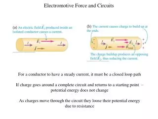
In a circuit a battery creates an electric field within and parallel to the wire. • Directed from the positive toward the negative terminal. • Electric field exerts a force on the free electrons in the wire, and they respond by moving. • Electric current: flow of charge. I = electric current, amount of charge per unit time that crosses the imaginary surface. Charges cross an imaginary surface that is perpendicular to their motion.
SI unit for current is a coulomb per second (C/s) • One coulomb per second is an ampere (A). • Andre-Marie Ampere, French • Direct current (dc): charges move around a circuit in the same direction at all times. • Ex. batteries • Alternating current (ac): charges move first one way and then the opposite way, changing direction from moment to moment. • Ex. Generators, microphones.
EXAMPLE 1: A POCKET CALCULATOR The battery pack of a pocket calculator has a voltage of 3.0V and delivers a current of 0.17mA. In one hour of operation, (a) how much charge flows in the circuit and (b) how much energy does the battery deliver to the calculator circuit?
Conventionalcurrent: flow of positive charges that would have the same effect in the circuit as the movement of negative charges that actually does occur. • Do not use the flow of electrons when discussing circuits. • a direction of conventional current is always from a point of higher potential toward a point of lower potential. • Positive toward the negative terminal. • I stands for conventional current.
20.2 OHM’S LAW • Current I is directly proportional to the voltage V. • 12V battery leads to twice as much current as a 6V battery.
Resistance (R): ratio of the voltage V applied across a piece of material to the current I through the material, R = V/I • When only a small current results from a large voltage, there is a high resistance to the moving charge. • Georg Simon Ohm
OHM’S LAW The ration V/I is a constant, where V is the voltage applied across a piece of material (such as a wire) and I is the current through the material: R is the resistance of the piece of material. SI Unit of Resistance: volt/ampere (V/A) = ohm
Resistor: extent that a wire or an electrical device offers resistance to the flow of charges. • Copper wires have a very small resistance. • Used to limit the amt. of current and establish proper voltage levels. • Symbol that represents resistors
EXAMPLE 2: A FLASHLIGHT The filament in a light bulb is a resistor in the form of a thin piece of wire. The wire becomes hot enough to emit light because of the current in it. Fig. 20.6 shows a flashlight that uses two 1.5V batteries to provide a current of 0.40 A in the filament. Determine the resistance of the glowing filament.
20.3 RESISTANCE AND RESISTIVITY • The resistance of a piece of material of length L and cross-sectional area A is.
p = proportionality constant known as the resistivity of the material. • Unit: ohm x meter • Table 20.1 (pg. 607) • Metals have small resistivities. • Semiconductors: germanium and silicon • Resistance depends on the resistivity and the geometry of the material. • Short wire with a large cross-sectional area has a smaller resistance than does a long, thin wire.
Wires that carry large currents, such as main power cables, are thick rather than thin so that the resistance of the wires is kept as small as possible. • Electric tools that are to be used for away from wall sockets require thicker extension cords.
EXAMPLE 3: LONGER EXTENSION CORDS The instructions for an electric lawn mower suggest that a 20-guage extension cord can be used for distances up to 35m, but a thicker 16-guage cord should be used for longer distances, to keep the resistance of the wire as small as possible. The cross-sectional area of 20-guage wire is 5.2 x 10^-7m^2, while that of 16-guage wire is 13 x 10^-7m^2. Determine the resistance of (a) 35m of 20-guage copper wire and (b) 75m of 16-guage copper wire.
Impedance (or resistance) plethysmography: used to diagnose blood clotting in the veins. • Electrodes are attached around the calf. The two outer electrodes are connected to a source of a small amount of ac current. • The two inner electrodes are separated by a distance L, and the voltage between them is measured. • Resistance is inversely proportional to volume. • More blood enters the calf than leaves.
Volume of the calf increases and the electrical resistance decreases. • With healthy veins, there is a rapid return to normal values when the cuff is removed. • Slow return reveals the presence of clotting.
The resistivity of a material depends on temperature. • Resistivity increases w/ increasing temp. in metals. • Semiconductors reverse is true • Express the temperature dependence of the resistivity in the following equation:
a temperature coefficient of resistivity • When the resistivity increases w/ increasing temp a is positive. (metals) • Resistivity decreases w/ increasing temp, a is negative, as it is for the semiconductors carbon, germanium, and silicon. • R = pL/A both sides multiplied by L/A, equation shows that resistance depends on temp.
EXAMPLE 4: THE HEATING ELEMENT OF AN ELECTRIC STOVE Wire L = 1.1m Cross sectional area = 3.1 x 10^-6m^2 po = 6.8 x 10^-5 To = 320 C a = 2.0 x 10^-3 C^-1 Determine the resistance of the heater wire at an operating temperature of 420 C.
Some materials resistivity suddenly goes to zero below a certain temperature Tc. • Called the critical temperature • Commonly a few degrees above absolute zero. • Below this temperature, such materials are called superconductors. • With zero resistivity, these materials off no resistance to electric current and are, therefore, perfect conductors.
Once a current is established in a superconducting ring, it continues indefinitely without the need for an emf. • The current in a nonsuperconducting material drops to zero almost immediately after the emf is removed.
Tc = 1.18K aluminum superconductor • Tc = 3.72K tin • Tc = 7.20K lead • used for MRI • Magnetic levitation of trains • Cheaper transmission of electric power • Powerful electric motors • Faster computer chips • http://www.youtube.com/watch?v=PSiQbyUyOlY
http://www.youtube.com/watch?v=xZU5ZSbLuHk&feature=related • http://www.youtube.com/watch?v=i0WtQHgl5oM
ELECTRIC POWER When electric charge flows from point A to point B in a circuit, leading to a current I, and the voltage between the points is V, the electric power associated with this current and voltage is P = IV (20.6) SI Unit of Power: watt (W)
Power is measured in watts. • Product of an ampere and a volt is equal to a watt. • When the charge moves through the device the charge loses electric potential energy. • Must be a transfer of energy. • Light energy, sound energy, thermal energy… • The charge in a circuit can also gain electrical energy. • Regains energy lost to the device, battery.
Electrical devices that are resistors that get hot when provided with electric power. • Ex. Toasters, irons, space heaters, …
EXAMPLE 5: THE POWER AND ENERGY USED IN A FLASHLIGHT In the flashlight in Fig. 20.6, the current is 0.40A, and the voltage is 3.0V. Find (a) the power delivered to the bulb and (b) the electrical energy dissipated in the bulb in 5.5 minutes of operation.
Energy is the product of power and time. • Companies compute energy consumption by expressing energy in kilowatt x hour (kWh). • Ex. Average power of 1440 watts (1.44kW) for 30 days (720h), your energy consumption would be (1.44kW)(720h) = 1040kWh. • Cost of $0.12 per kWh, your monthly bill would be $125. • 1kWh = 3.60 x 10^6J
20.5 ALTERNATING CURRENT • Charge flow reverses direction periodically. • Generators • Voltage produced between the terminals of the ac generator at each moment of time t.
Vo = maximum or peak value of the voltage F = frequency (in cycles/s or Hz) Calculator set on radians. Most oscillates with a frequency of f = 60Hz 1/60sec. Vo = 170 V
Substituting V = Vo sin 2πft into V = IR shows the current can be represented as
Power delivered to an ac circuit by the generator is given by P = IV Since both I and V depend on time, the power fluctuates as time passes. Substituting Equations 20.7 and 20.8 for V and I into P = IV gives.
Since the power fluctuates in an ac circuit, it is customary to consider the average power P, which is one-half the peak power as fig 20.12 indicates.
On the basis of this expression, a kind of average current and average voltage can be introduced that are very useful when discussing ac circuits. A rearrangement of Eq. 20.10 reveals that.
Irms and Vrms are called the root mean square (rms) current and voltage, respectively, and may be calculated from the peak values by dividing them by √2