Download
1 / 61
620 likes | 777 Views
Electric Energy and Circuits. Chapter 15. Potential Difference. Recall potential energy – the amount of energy an object could have due to its position. Ex. A book on a desk vs on the floor, a sky diver on the ground or 5000 ft in the air. The potential to move implies stored energy.

E N D
Electric Energy and Circuits Chapter 15
Potential Difference • Recall potential energy – the amount of energy an object could have due to its position. • Ex. A book on a desk vs on the floor, a sky diver on the ground or 5000 ft in the air. • The potential to move implies stored energy. • For an electric current to operate there must be a difference in the amount of energy.
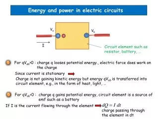
The electric potential difference between any two points in a circuit is the quotient of the change in the electric potential energy of charges passing between those points and the quantity of the charge. • Electric potential difference - V or volt • Change in electrical potential energy - ΔEQ, measured in joules • Charge - q measured in Coulombs
One joule per coulomb is equal to one volt. • Recall from Physics 521 work and energy are interchangeable. Work = ΔEnergy
Variations of the formula for finding the electric potential difference. • 1 Volt = 1 Newton-meter/Coulomb = J/C
Do Sample Problem on Page 691 • Do Practice Problems on Page 692 #s 1-3
Electric Current • When the ends of a conductor are at different potentials (voltage), charge flows from the region of higher potential to the region of lower potential across the ends of the conductor. • The flow of charges will continue until both ends of the conductor reach the same potential, at which time it will stop flowing.
To continue a flow of charge in a conductor, a difference of potential must be maintained across the ends of the conductor. • This requirement is provided by an “power supply” (for example, a battery converts chemical energy into electrical energy; a solar cell converts light energy into electric energy; a generator converts mechanical energy into electrical energy).
External energy from the pump sets up a potential difference between the two ends of the conductor by maintaining a constant negative charge in one area and a constant positive charge in another area (terminals of a battery). • If these 2 points, at a different potential, are connected by a conducting wire, electric charge will flow from an area of high potential energy to the area of low potential energy within a closed loop called an electric circuit.
A circuit consists of a device which continuously increases the PE of the charges (power supply) connected to a device (load) that continuously reduces the PE of the charges by providing resistance to their movement (i.e. electric motor). • This loss of PE of the charges as they move through the circuit can be converted into other forms of energy (i.e. a motor converts electric energy into kinetic energy and a lamp converts electric energy into light energy).
Electric pumps do not create electric charges or electrons, but only provide energy to move them through a circuit. • The total amount of charge or energy in a circuit never changes; it is conserved. • In any circuit, the PE increase (qV) provided by the charge pump (battery) equals the PE decrease as the current moves through a resistance (i.e. motor) because of the Law of Conservation of Energy.
When the flow takes place in one direction, it is called direct current (DC); and when it flows back and forth it is called alternating current (AC). • open circuit- there is a break somewhere in the circuit which prevents current from flowing (i.e. an open switch). • closed circuit- all connections are complete and current flows.
Current vs Electron Flow • Early concepts (early 1800s) of current electricity “assumed” a positive current. • JJ Thomson discovered the electron in 1901 and then scientists realized that it was the negative electron that was moving. • However, current (I) means the flow of positive charges from anode (+) to cathode (-) in a circuit. • The electron flow is from cathode (-) to anode (+).
The electric current is the flow of charges per unit of time. • Current – I measured in amperes (A) • Charge – q measured in coulombs (C) • Time interval – Δt measured in seconds (s)
Do Sample Problem on Page 695 • Do Practice Problems on Page 696 #s 4-11
Current and the Elementary Charge • Current is the flow of charges. • Elementary charge (e) is the amount of charge on 1 electron – 1.60 × 10⁻¹⁹ C. • (Also the proton is + 1.60 × 10⁻¹⁹ C.) q = Ne • Do Model Problem on Page 699 • Do Practice Problems on Page 700 #s 12-15
Electric Circuits • Schematic diagram- diagram of an electric circuit using standard symbols for the electric circuit components (Figs. 15.10-15.12 on Page 701). • See Conceptual Problems on Page 702
Steps for Drawing Schematic Diagrams • 1. Draw the battery symbol on the left side of the page; put the positive terminal on top. • 2. Draw a wire connecting the conventional current out of the positive terminal. When you reach a resistor or another device, draw the symbol for it. • 3. If you reach a point where there are 2 or more current paths (i.e. a voltmeter), draw in the diagram and follow one path until the two paths join again, then draw the second path. • 4. Follow the path until you get to the negative terminal of the battery. • 5. Check your drawing to ensure you have included all parts and that the current paths are complete. • The direction of current flow is the direction that positive charges would move (this is called conventional current).
Types of Electric Circuits • Series Circuit- a method of connecting all circuit elements (loads and power source) which provides only one path through which current can flow. • Parallel Circuit- a method of connecting two or more circuit elements between 2 points which provides more than one current path.
Ammeters and Voltmeters • An ammeter, which measures the amount of current, must be connected in series (same path as everything else) to give an accurate reading of current flow. • A voltmeter, which measures the potential difference across a circuit device, must be attached in parallel (with one terminal on each side of the device across which it is measuring the potential difference). • The potential difference across the device equals the potential difference across the voltmeter. • See Figure 15.13 on Page 703
ResistanceSection 15.3 • Voltage is an electrical pressure that can produce current (a flow of charge) within a conductor. • The amount of current that will flow in a circuit depends on the potential difference (voltage) across the circuit and the resistance the conductor (circuit) provides the moving charges.
Resistance(R) - the obstruction or resistance to the flow of electrical charges in a circuit. • Fixed Resistor- a device designed to have a specific resistance. It is used to control the current in circuits or parts of circuits. • Variable Resistor- also called a rheostat or potentiometer- a device consisting of a coil of resistance wire and a sliding contact point. • This allows for varied amounts of current to flow in the circuit according to the equation V = IR. • Ex: fans with different speeds and dimming lights.
Factors Affecting Resistance in Electric Conductors • Resistance increases proportionately with the length. • Resistance varies inversely as the cross-sectional area.
By combining these proportionalities and using the resistivity constant, we get the following equation for the resistance of a conductor: • Resistance is measured in ohms. • Resistivity() - measured in ∙m (See Table 15.1)
The resistance of a conductor also depends on the conductivity of material used and its temperature (a short, thick, cold conductor reduces resistance). • Note that superconductors have zero resistance and therefore, no voltage drop across them.
Do Sample Problem on Page 707 • Do Practice Problems on Page 708 #s 16 - 20
Ohm’s Law • Ohm’s Law states that the resistance of an object is constant and independent of the voltage across it....the potential difference across a load equals the product of the current through the load and the resistance of the load (limited to metal conductors at stable temperatures).
Ohm (Ω)- resistance of a device that allows current of 1 amp to flow when a potential difference of 1 volt is applied across the resistance. 1 Ω= 1Volt/Amp • Ohm’s Law means that the current in a circuit , kept at a constant temperature, is directly proportional to the voltage across a circuit and inversely proportional to the resistance of the circuit. Therefore, the greater the voltage, the greater the current and the greater the resistance, the lesser the current.
Since I = V/R, the current flowing through a circuit can be regulated in 2 ways: • 1. increase or decrease the voltage across the circuit (i.e. to get a stronger charge pump or use more batteries). • 2. increase or decrease the resistance of the circuit using devices called resistors. • If a device doesn’t obey Ohm’s Law, the graph of I versus V is non-linear (non-ohmic).
Do Sample Problem on Page 713 • Do Practice Problems on Page 714 #s 21 - 26
Series and Parallel CircuitsSection 15.4 • Series Circuit – a complete path for current to flow in which the electrical devices form a single path. • Parallel Circuit –a circuit in which there are 2 or more paths for current to flow.
Series Circuits • A break anywhere in the path stops current flow in the entire circuit. • The total resistance of the circuit equals the sum of the individual resistors. • The current (I) equals the voltage provided by the source (V) divided by the total resistance (R). • The voltage drop (potential difference) across each device is proportional to its resistance since more energy is needed to move charges through a large resistance. (V=IR)
The sum of the voltage drops across the resistance of each device is equal to the total voltage supplied by the source. V = V1 + V2 + V3 + ... + VN (VN to represent any number of sources) Since V = IR Then V= IR1 + IR2 + IR3 + ... + IRN So then V = I(R1 + R2 + R3 + ... + RN) Therefore I = V/(R1 + R2 + R3 + ... + RN)
The same current will exist in a series circuit with a single resistor that has a resistance equal to the sum of the individual resistances. • The number of electrons moving or flowing (I) does not change. • Equivalent resistance (Req) – a single resistance that has the same effect as a number of resistances in a series circuit. It is larger than any single resistance. Req = R1 + R2 + R3 + ... + RN
To find the current with multiple resistors you should first find Req then use I = V/Req. • The net change in electrical potential around the series circuit must be zero. • The charge pump increases the PE of the charges but each resistor decreases the PE of the charges. • This results in a net electrical potential change of zero.
To find the potential drop across each resistor in series you must use the equivalent resistance (Req) to find current (I), then you multiply I by the resistance of each individual device to find the potential drop across each device.
Do Model Problem on Page 718 • Do Practice Problems on Page 719 - 720 #s 27-31
Parallel Circuits • The potential difference across each path is the same because each device connects the same two points of the parallel circuit. • The total current is divided among the parallel branches. Current passes more readily into low resistors so that current (I) is inversely proportional to R (smaller R, more I). I = V/R • The total current is the sum of the currents through each path. I = I1 + I2 + I3
As the number of parallel branches increases, the overall resistance of the circuit decreases. • To find the current through each branch: I1 = V/R1 • To find the total current: I = V/R1 + V/R2 + V/R3 I = V(1/R1 + R2 + R3)
Equivalent resistance (1/Req) of three parallel resistors: • The Req in a parallel circuit is less than the resistance of any resistor in the circuit.
Do Model Problem on Page 722-724 • Do Practice Problems on Page 724 #s 32-35
Electric Circuit Overloads • An electric circuit overload may occur when too many current drawing devices are connected in parallel. • The overall resistance is reduced with each device added in parallel, so more current is allowed to flow. • This adds sufficient thermal energy which may melt insulation on wires causing a short circuit when bare wires touch.
Short Circuit - a very low resistance connection between 2 points in a circuit where the resistance should be very high. • Fuse – a safety device, added in series, which melts to stop current flow when it becomes too large. • Circuit Breaker – an automatic switch that opens when the current meets a certain value. If a current that is greater than the set value flows, then it will overload and the circuit breaker opens to stop all current flow.
Series – Parallel Combination Circuits • Steps • If any resistors are in parallel, calculate the equivalent resistance that would replace them. • If any equivalent resistors are now connected in series, calculate a new equivalent resistance that can replace them. • Repeat steps 1 & 2 until you can reduce the circuit to 1 resistor then find the current through the entire circuit. Finally, the voltage drops and current through each resistor can be found.
Diagrams • Series Circuit • Parallel Circuit
Recall definitions of ammeters and voltmeters. • In an ammeter, the resistance should be as low as possible so it does not change the current. • In a voltmeter, the resistance should be high so the current does not go through the voltmeter.
Do Your Ohmwork (worksheet) • True/False worksheet • Do Sample Problem on Pages 725- 727 • Do Practice Problems on Page 728 #s 36 & 37
Energy Transfer in Electric Circuits • As we have seen earlier, electrical energy can be transferred into other forms of energy. • Electrical power (the power of an electrical appliance) measures the rate at which electric charge or energy is transferred in a circuit (rate appliance does work). • For resistors that obey Ohm’s Law, power equals the potential difference (Volts) across a circuit multiplied by the current (Amps).
When a battery converts one Joule of chemical energy to electrical energy per second, then the rate of transfer (power) is 1 J/s or 1 Watt (W). • Power is determined by multiplying the potential difference across the appliance (V) by the current (I) moving through the appliance expressed in a term called Watts (J/s).