Initial Results from the current ARIES Power Plant Study
190 likes | 332 Views
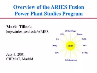
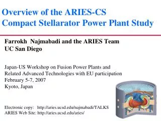
Initial Results from the current ARIES Power Plant Study. Farrokh Najmabadi UC San Diego Japan/US Workshop on Power Plant Studies and Related Advanced Technologies With EU and Korea Participation 22-24 February 2011 NIFS, Japan.

Initial Results from the current ARIES Power Plant Study
E N D
Presentation Transcript
Initial Results from the currentARIES Power Plant Study Farrokh Najmabadi UC San Diego Japan/US Workshop on Power Plant Studies and Related Advanced Technologies With EU and Korea Participation 22-24 February 2011 NIFS, Japan
Resolving the PMI and HHC issues is a priority for the US Community • ITER faces difficult choices re PMI and High-Heat Flux components • Considerable change in predictions of heat and particle fluxes on in-vessel components • ARIES Designs were done in the context of the best available information at the time (ARIES-AT is ~10 years old). • There is a considerable confusion re capability of various components to handle heat/particle fluxes, i.e., in many cases peak transient heat fluxes are compared with the steady-state heat-flux capabilities. • An integrated solution should be found that does not transfer the problem to another system in the power plant.
Goals of Current ARIES Study • Revisit ARIES Designs with a focus on detailed analysis edge plasma physics and plasma-material interaction, high heat flux components and off-normal events in a fusion power plant. • What would ARIES designs look like if we use current predictions on heat/particles fluxes? • What would be the maximum fluxes that can be handled by in-vessel components in a power plant? • What level of off-normal events are acceptable in a commercial power plant? • Can the current physics predictions (ITER rules, others) be accommodated and/or new solutions have to be found?
Frame the “parameter space for attractive power plants” by considering the “four corners” of parameter space Reversed-shear (βN=0.04-0.06) DCLL blanket Reversed-shear (βN=0.04-0.06) SiCblanket ARIES-RS/AT SSTR-2 EU Model-D Higher power density Higher density Lower current-drive power Physics Extrapolation Decreasing P/R 1st Stability (no-wall limit) DCLL blanket 1st Stability (no-wall limit) SiCblanket Lower power density Lower density Higher CD power ARIES-1 SSTR Lower thermal efficiency Higher Fusion/plasma power Higher P/R Metallic first wall/blanket Higher thermal efficiency Lower fusion/plasma power Lower P/R Composite first wall/blanket
Study is divided into Two Phases: • Project began in Jan. 2010. • Phase 1: • Examination of power-plant parameter space with the systems code to understand trade-offs. • Examination of capabilities of in-vessel components (heat and particle fluxes) in both steady-state and off-normal events, e.g., ELM, disruption (thermal). • Phase 2: • Detailed design • To verify systems code predications • To develop an integrated design • To document trade-offs and R&D needs.
Progress to date: • Examination of power-plant parameter space with the systems code to understand trade-offs. • Systems code development near completion. • Data visualization tool was developed. • Plan is to generate systems data base in the next 3 months. • Examination of capabilities of in-vessel components (heat and particle fluxes) in both steady-state and off-normal events, e.g., ELM, disruption (thermal). • Design improvements (e.g., Optimized T-tube slot & manifold, Modified finger configuration, Optimized jet layout for fingers) • Detailed analysis to understand capability (e.g., Elastic-plastic analysis, Thermal hydraulics of plate concept with pin fins, preliminary analysis of transient.
Systems code development See L. Carlson Presentation for Systems Code Data visualization tool.
ARIES Systems Code are used for trade-off analysis • In principle, ARIES studies have used systems code to understand trade-offs and NOT as a design tool: • It is impossible at the present to combine all analysis tools of various components into one package. Systems code, therefore, includes simple and reasonably accurate model of various subsystems. • We use Systems code as an iterative tool during the design process: systems code identifies the area of interest in the parameter space, detailed design of a “preliminary” design point (“strawman”) helps to identify issues and refine systems code models, systems code identifies a new “strawman,” etc. • Typically, we have used COE as the object function for systems analysis while other objectives/constraint were included in the design process.
Issues with Systems Code “Mathematical” minimum Optimum region Systems code accuracy • Better Approach: Indentify “optimum region ” as opposed to the optimum point. Experience indicates that the power plant parameter space includes many local minima and the optimum region is quite “shallow.” The systems code indentifies the “mathematical” optimum. There is a large “optimum” region when the accuracy of the systems code is taken into account, requiring “human judgment” to choose the operating point. Previously, we used the systems code in the optimizer mode and used “human judgment” to select a few major parameters (e.g., aspect ratio, wall loading).
New ARIES Systems Code • New “optimization” approach: • Indentify “optimum” parameters space as opposed to the optimum point. • In addition, experience indicates that “optimum” design points are usually driven by the constraints. In some cases, a large design window is available when the constraint is “slightly” relaxed, allowing a more “robust” and credible design. • Developed a new approach to Systems Analysis based on surveying the design space instead of finding only an optimum design point (e.g., lowest COE). • This approach requires generation a very large data base of self-consistent physics/engineering points. • Modern visualization and data mining techniques are used to explore design space.
Example: Impact of field strength SiC Blanket Bt < 7 T Bt < 5 T COE (mills/kWh) COE (mills/kWh) Heat flux on in board divertor (MW/m2) Heat flux on in board divertor (MW/m2) • For a given maximum bN: • A minimum Bt is required • Larger Bt typically increase the size of parameter space (e.g., relax many parameters, bN, nG/n, H98, …) but does not reduce the minimum cost.
Major Features of the new ARIES Systems Code • Detailed 2-D axisymmteric geometry based on plasma shape and includes maintenance considerations. • Detailed power flow. • TF Magnet algorithm bench-marked against finite-element analysis of ARIES magnets. • Distributed PF algorithm which produces accurate description of stored energy, cost, and VS of a free-boundary equilibrium-based PF system. • New costing algorithm • Based on Gen-IV costing rules.
High-heat-flux components See M. Tillack Presentations for details
Advanced Helium-Cooled W-alloy Divertor Designs • Temperature and stress limits are the reason for heat flux limits on plasma-facing components. • Advanced design concepts attempt to improve heat transfer (with acceptable pressure drop) and maintain stresses within allowable limits for materials in our portfolio. • Fabricability, maintainability and reliability are always at the heart of new design ideas. • ARIES is moving toward full time-dependent engineering analyses accounting for fabrication steps, normal and off-normal operating modes. • Higher heat-flux limits; • major implications for material data base and testing needs.
Advanced Helium-Cooled W-alloy Divertor Designs T-Tube • T-Tube divertor: ~1.5 cm dia. X 10 cm long • Impinging-jet cooling • Allowable heat flux>10 MW/m2 • ~110,000 units for a power plant Finger • EU finger: 2.6 cm diameter • Impinging multi-jet cooling • Allowable heat flux>15 MW/m2 • ~535,000 units for a full power plant
Advanced Helium-Cooled W-alloy Divertor Designs Plates with jet and/or pin-fin cooling • Plate-type divertor: 20 cm x 100 cm • Impinging-jet cooling • Allowable heat flux ~10 MW/m2 • ~750 units for a power plant Finger/plate combinations • Combination of the plate and EU finger divertor • Fingers for q >8 MW/m2 • Plate for q < 8 MW/m2 • Increased design margin and reduced number of finger units
In Summary… • ARIES studies is focusing ondetailed analysis edge plasma physics and plasma-material interaction, high heat flux components and off-normal events in a fusion power plant. • Study started in Jan. 2010. • Phase 1 of study aims at • Examination of power-plant parameter space with the systems code to understand trade-offs. • New ARIES Systems Code • Examination of capabilities of in-vessel components (heat and particle fluxes) in both steady-state and off-normal events, e.g., ELM, disruption (thermal). • Detailed analysis of advanced He-cooled W-alloy divertor design