Download
1 / 31
330 likes | 523 Views
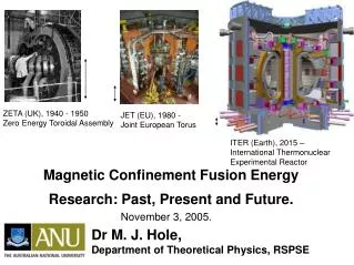
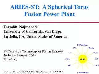
ARIES-ST: A Spherical Torus Fusion Power Plant. Farrokh Najmabadi University of California, San Diego, La Jolla, CA, United States of America 9 th Course on Technology of Fusion Reactors 26 July – 1 August 2004 Erice Italy

E N D
ARIES-ST: A Spherical Torus Fusion Power Plant Farrokh Najmabadi University of California, San Diego, La Jolla, CA, United States of America 9th Course on Technology of Fusion Reactors 26 July – 1 August 2004 Erice Italy Electronic Copy: ARIES Web Site: http://aries.ucsd.edu/PUBLIC
Larger extrapolation from present COE has a “hyperbolic” dependence ( 1/x) and improvements “saturate” after certain limit Stay close to present-day Translation of Requirements to GOALS for Fusion Power Plants‡ Requirements: • Have an economically competitive life-cycle cost of electricity: • Low recirculating power (Increase plasma Q, …); • High power density (Increase Pf ~ b2BT4 , …) • High thermal conversion efficiency; • Less-expensive systems. • Gain Public acceptance by having excellent safety and environmental characteristics: • Use low-activation and low toxicity materials and care in design. • Have operational reliability and high availability: • Ease of maintenance, design margins, and extensive R&D. • Acceptable cost of development. ‡ See ARIES-AT lecture in this course
Almost Constant for BT fixed at the TF coil eBT2 • For Superconducting Tokamaks, it is b/e (i.e.,bR/a) that is important, not b. • Fusion power density, Pf ~ b2BT4 = (b/e)2(eBT2)2 • Power density is roughly independent of A Pf ~ b2BT4 • b scales inversely with aspect ratio A=R/a • Reduce A to increase b and Pf • For very low aspect ratio (A < 2), b may become large enough that a superconducting TF coil would be unnecessary. STs • Potential for small devices e = a/R=1/A Directions for Increasing Fusion Power Density
ARIES-ST Study: Assessment of ST as power plants • Question: What is the optimum regime of operation for tokamaks with resistive coils: • for power plants (Joule losses in TF is critical); • for fusion development or non-electric applications (Joule losses in TF may not be as critical).
Key Physics Issues for Spherical Tokamaks • Because of low aspect ratio, the area in the inboard is limited. To minimize the Joule losses, this area should be entirely used for the inboard leg of the TF coils (center-post). • Because there is no room for a central solenoid, steady-state operation is mandatory. • In order to minimize the Joule losses in the TF coils (mainly the center-post), MHD equilibria with very high b are required. • Because of large plasma current, only MHD equilibria with almost perfect bootstrap alignment would lead to a reasonable current-drive power. • Because of unique magnetic topology, on-axis current drive with RF techniques is difficult. Current drive for profile control as well as start-up are additional challenges. • The divertor problem is more difficult than conventional and advanced tokamaks (higher P/R).
Key Engineering Issues for Spherical Tokamaks • The small area available for the inboard legs of the TF coils (center-post) make the design of center-post challenging. • While the field in the plasma center is low, the field on the inboard leg of the TF coils (center-post) would be very high (due to 1/R dependence). • Large forces on the center-post • Potential advantages of spherical tokamaks (compact) make the engineering of fusion core difficult: • Because of large recirculating power, a highly efficient blanket design is essential; • Water-cooled copper coils further narrow the options; • High heat flux on in-vessel components further narrows the options; • Highly shaped components (tall and thin) make mechanical design difficult. Tritium breeding may also be an issue. • Maintenance of the power core should include provisions for rapid replacement of center-post.
ARIES-ST Physics Summary • A data base of high-b equilibria with 100% bootstrap fraction was developed and used for trade-off studies. • The final design point has A = 1.6 (a board COE minimum for A=1.4 to 1.7) with a toroidal b = 50% with a high elongation (kx= 3.75) and high triangularity (dx= 0.67). • Such a highly shaped plasma is necessary to increase b and have a reasonable TF Joule losses. • Low-A free-boundary equilibria is unique and difficult to calculate because of strong B variation; strong plasma shaping (k ~ 3 , d ~ 0.5); and high bp (~2) and low li (~0.15). • PF coils are internal to TF coil to have a reasonable stored energy. • An acceptable plasma start-up sequence, utilizing bootstrap current overdrive was developed. (There is no OH solenoid).
ARIES-ST Physics Summary • Low-energy (120 keV) neutral beam is used to drive current at plasma edge and induce plasma rotation. • It appears that LFFW is the only plausible RF technique that drives current near the axis on high-b ST plasmas • Because wpe/ wce >>1, EC and LH waves cannot access the plasma center. • HFFW does not penetrate to the center because of strong electron and/or ion damping; • ICRF fast wave suffer strong electron and a/ion damping. • LFFW requires a large antenna structure for a well-defined spectrum (l|| ~ 14 m). It generally has a fairly low current-drive efficiency. • Current-drive near the axis may be unnecessary because of “potato” orbit effect. • Plasma is doped with impurities in order to reduce the heat load on the divertor plates. The plasma core radiation was limited by heat flux capability of the inboard first wall (~1 MW/m2).
Parameters of ARIES-ST Aspect ratio 1.6 Major radius 3.2 m Minor radius 2 m Plasma elongation, kx 3.75 Plasma triangularity, dx 0.67 Plasma current 28 MA Toroidal b 50% Toroidal field on axis 2.1 T Avg. neutron wall load 4.1 MW/m2 Fusion power 2980 MW Recirculating power 520 MW TF Joule losses 325 MW Net electric output 1000 MW
Spherical Tokamaks Are Quite Sensitive to Physics/Engineering Trade-off • The physics and engineering trade-off are most evident in determining the inboard radial built: • Smaller radial built -> improved plasma performance; • Larger radial built -> engineering credibility; • Every centimeter counts! • Challenge: maximize physics performance while maintaining a credible design.
Electrical Design of the Center-post : Options • The conductor should be able support the mechanical loads to maximize the packing fraction. • Leading conductor material is Glidcop AL-15. • It has adequate strength, ductility, low swelling, and thermal and electrical conductivities; • Under irradiation, it suffers from severe embrittlement (at room temperature); • Hardening and embrittlement are alleviated by operating above 180oC but then it suffers from severe loss of fracture toughness. • The ARIES-ST reference case is to operate Glidcap at room temperature. • Single-turn TF coils are preferred in order to reduce Joule heating • Higher packing fraction; • Reduced shielding requirement (no insulation); • Requires high-current low-voltage supplies with massive busbars.
Mechanical Design of the Center-post: Options • Sliding electrical joints are employed between center-post and other TF legs and bus-bars and TF legs. • They allow relative motion in radial and vertical directions (which minimizes axial loads on the center-post); • They enhance maintainability; • Several design options have been developed and tested successfully. • Center-post is physically separate from other components in order to avoid a complex interface.
Thermal-hydraulic Design of the Center-post : Options • Cry-cooling does not offer major improvement over cooling options at room temperature and above. • Water cooling is the leading option: • Low-temperature operation (Tinlet~ 35C) minimizes Joule losses but results in severe embrittlement of conductor; • High-temperature (Tinlet~ 150 to 180C) avoids embrittlement but lose of fracture toughness and increased Joule losses are key issue.). • Liquid lithium (both conductor and coolant) is probably the best option for high-temperature operation. However, in addition to many challenging engineering issues, recovery of center-post heating does not offset increased Joule losses.
TF Coil System Is Designed for Vertical Assembly • Water-cooled center-post is made of DS GlidCop AL15. • Outboard TF coil form a shell to minimize mechanical forces and minimize field ripple. • Center-post is connected to the TF shell through a tapered joint on the top and sliding joints at the bottom. • Insulating joint is located at the outboard mid-plane where the forces are smallest. • Another TF joint is provided for vertical maintenance of the power core.
The TF Shell Also Acts As the Vacuum Vessel • TF shell is made of Al to reduce the cost. It also acts as the vacuum vessel. • Large TF leads are used to minimize the Joule losses and also minimize toroidal-field error. • Power supplies are located very close to the power core.
A Thin Inboard Shield Is Desirable • Perception: Inboard shields lead to higher Joule losses and larger & more expensive ST power plants. • A thin (15-20 cm) shield actually improves the system performance: • Reduces nuclear heating in the center-post and allows for a higher conductor packing fraction; • Limits the increase in the electrical resistivity due to neutron-induced transmutation; • Improve power balance by recovering high grade heat from shield; • Allow center-post to meet low-level waste disposal requirement with a lifetime similar to the first wall. (More frequent replacement of center-post is not required.)
Transmutation of Cu Changes the Center-post Resistivity • Dominant Cu transmutation products are Ni, Zn, and Co • 64Ni and 62Ni dominate the change in resistivity Resistivity changes with a 30-cm, 80% dense Ferritic Steel/He shield
A Thin Inboard Shield Is Desirable • Perception: Inboard shields lead to higher Joule losses and larger & more expensive ST power plants. • A thin (15-20 cm) shield actually improves the system performance: • Reduces nuclear heating in the center-post and allows for a higher conductor packing fraction; • Limits the increase in the electrical resistivity due to neutron-induced transmutation; • Improve power balance by recovering high grade heat from shield; • Allow center-post to meet low-level waste disposal requirement with a lifetime similar to the first wall. (More frequent replacement of center-post is not required.)
ARIES-ST Inboard First Wall/Shield Design Surface heating 125 MW Nuclear heating 285 MW Structure Steel Coolant 12 MPa He He Inlet Temp. 300oC He Outlet Temp. 510oC
ST Plasma Shape Leads to Unique Design Features • Plasma is highly elongated. • High plasma triangularity does not allow for center-post flaring. • There is no inboard divertor plate/slot. • Combination of highly elongated power core and large outboard TF legs leads naturally to vertical maintenance and has a dramatic impact on ARIES-ST configuration.
Spherical Torus Geometry Offers Some Unique Design Features (e.g., Single-Piece Maintenance)
Vertical Maintenance from the Bottom Is Preferred • Reduced building height & size. • Radioactive material are confined to the maintenance area. • More accurate positioning with lifts compared to cranes.
The ARIES-ST Performance Is NOT Limited by First Wall/Blanket Capabilities • The ARIES-ST wall loading of 4 MW/m2 (average) is lower than ARIES-RS due to the trade-off between recirculating power and compactness. In fact, simple geometrical arguments shows that there is little economic incentive to go beyond 5 to 10 MW/m2 of wall load for any 1000-MWe fusion power plants. • Average neutron wall loading 4.1 MW/m2 • Peak neutral wall loading 6.0 MW/m2 • Average surface heat flux (OB first wall) 0.5 MW/m2 • Surface heat flux capability (first wall) 0.9 MW/m2 • Surface heat flux capability (W stabilizers) 2.0 MW/m2 • Peak heat flux (divertor) 6.0 MW/m2
OB Blanket thickness 1.35 m • OB Shield thickness 0.42 m • Overall TBR 1.1 ARIES-ST Features a High-Performance Ferritic Steel Blanket • Typically, the coolant outlet temperature is limited to the maximum operating temperature of structural material (550oC for ferritic steels). • By using a coolant/breeder (LiPb), cooling the structure by He gas, and SiC insulators, a coolant outlet temperature of 700oC is achieved for ARIES-ST leading to 45% thermal conversion efficiency.
Coolant Flow Is Chosen Carefully to Maximize Coolant Outlet Temperature Power in Steel 330 MW Power in LiPb 1614 MW He pressure 12 MPa He inlet 300 oC He Outlet 525 oC LiPb Inlet 550 oC LiPb Outlet 700 oC
Advanced Manufacturing Techniques Can Reduce the Cost of Fusion Dramatically • Because of the large mass, the cost ARIES-ST TF coils were estimated to be comparable to the ARIES-RS superconduting coils. • Components manufacturing cost can be as high as 10 to 20 times of the raw material cost. For ARIES-ST center-post, the unit cost was estimated at $60/kg compared to $3/kg for copper. • New “Rapid Prototyping” techniques aim at producing near finished products directly from raw material (powder or bars) resulting in low-cost, accurate, and reliable components. • A Boeing study showed that the cost of ARIES-ST TF coils were substantially reduced (to about $8/kg) using these techniques.
AeroMet has produced a variety of titanium parts as seen in attached photo. Some are in as-built condition and others machined to final shape. Laser or Plasma Arc Forming • A laser or plasma-arc deposits a layer of metal (from powder) on a blank to begin the material buildup. • The laser head is directed to lay down the material in accordance with a CAD part specification.
Good Material Properties Can Be Obtained • Fatigue testing performed on laser formed Ti-6Al-4V, showing performance at the low end of wrought material. Plotted against standard axial fatigue zones of cast and wrought Ti-6Al-4V, Ref Aeromet and DARPA.
Molten Metal Furnace, Courtesy of SECO/WARWICK, Inc Schematic of Spray Casting Process
Highlights of ARIES-ST Study • Substantial progress is made towards optimization of high-performance ST equilibria, providing guidance for physics research. • 1000-MWe ST power plants are comparable in size and cost to advanced tokamak power plants. • Spherical Torus geometry offers unique design features such as single-piece maintenance. • A feasible water-cooled center-post with reasonable Joule losses is developed. • A 20-cm inboard first wall/shield is utilized. This shield makes the center-post design credible with no cost penalty. • A high-performance ferritic steels blanket was developed. • Advanced manufacturing techniquescan reduce the cost of fusion dramatically. • Modest size machines can produce significant fusion power, leading to low-cost development pathway for fusion.