Download
1 / 44
440 likes | 537 Views
Explore TCP's bi-directional data flow, reliability in byte streams, and congestion control techniques. Learn about MSS, handshaking, point-to-point communication, and efficient data transfer. Understand TCP's segment structure, flow control mechanisms, and timeout settings for optimal performance.

E N D
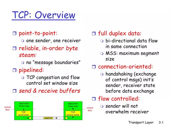
full duplex data: bi-directional data flow in same connection MSS: maximum segment size connection-oriented: handshaking (exchange of control msgs) init’s sender, receiver state before data exchange flow controlled: sender will not overwhelm receiver point-to-point: one sender, one receiver reliable, in-order byte steam: no “message boundaries” pipelined: TCP congestion and flow control set window size send & receive buffers TCP: Overview Transport Layer
32 bits source port # dest port # sequence number acknowledgement number head len not used Receive window U A P R S F checksum Urg data pnter Options (variable length) application data (variable length) TCP segment structure URG: urgent data (generally not used) counting by bytes of data (not segments!) ACK: ACK # valid PSH: push data now (generally not used) # bytes rcvr willing to accept RST, SYN, FIN: connection estab (setup, teardown commands) Internet checksum (as in UDP) Transport Layer
Seq. #’s: byte stream “number” of first byte in segment’s data ACKs: seq # of next byte expected from other side cumulative ACK Q: how receiver handles out-of-order segments A: TCP spec doesn’t say, - up to implementor time TCP seq. #’s and ACKs Host B Host A User types ‘C’ Seq=42, ACK=79, data = ‘C’ host ACKs receipt of ‘C’, echoes back ‘C’ Seq=79, ACK=43, data = ‘C’ host ACKs receipt of echoed ‘C’ Seq=43, ACK=80 simple telnet scenario Transport Layer
Q: how to set TCP timeout value? longer than RTT but RTT varies too short: premature timeout unnecessary retransmissions too long: slow reaction to segment loss Q: how to estimate RTT? SampleRTT: measured time from segment transmission until ACK receipt ignore retransmissions SampleRTT will vary, want estimated RTT “smoother” average several recent measurements, not just current SampleRTT TCP Round Trip Time and Timeout Transport Layer
Example RTT estimation: Transport Layer
TCP Round Trip Time and Timeout EstimatedRTT = (1- )*EstimatedRTT + *SampleRTT • Exponential weighted moving average • influence of past sample decreases exponentially fast • typical value: = 0.125 Transport Layer
Setting the timeout EstimtedRTT plus “safety margin” large variation in EstimatedRTT -> larger safety margin first estimate of how much SampleRTT deviates from EstimatedRTT: TCP Round Trip Time and Timeout DevRTT = (1-)*DevRTT + *|SampleRTT-EstimatedRTT| (typically, = 0.25) Then set timeout interval: TimeoutInterval = EstimatedRTT + 4*DevRTT Transport Layer
TCP creates rdt service on top of IP’s unreliable service Pipelined segments Cumulative acks TCP uses single retransmission timer Retransmissions are triggered by: timeout events duplicate acks Initially consider simplified TCP sender: ignore duplicate acks ignore flow control, congestion control TCP reliable data transfer Transport Layer
data rcvd from app: Create segment with seq # seq # is byte-stream number of first data byte in segment start timer if not already running (think of timer as for oldest unacked segment) expiration interval: TimeOutInterval timeout: retransmit segment that caused timeout restart timer Ack rcvd: If acknowledges previously unacked segments update what is known to be acked start timer if there are outstanding segments TCP sender events: Transport Layer
NextSeqNum = InitialSeqNum SendBase = InitialSeqNum loop (forever) { switch(event) event: data received from application above create TCP segment with sequence number NextSeqNum if (timer currently not running) start timer pass segment to IP NextSeqNum = NextSeqNum + length(data) event: timer timeout retransmit not-yet-acknowledged segment with smallest sequence number start timer event: ACK received, with ACK field value of y if (y > SendBase) { SendBase = y if (there are currently not-yet-acknowledged segments) start timer } } /* end of loop forever */ TCP sender(simplified) • Comment: • SendBase-1: last • cumulatively ack’ed byte • Example: • SendBase-1 = 71;y= 73, so the rcvrwants 73+ ;y > SendBase, sothat new data is acked Transport Layer
Host A Host B Seq=92, 8 bytes data ACK=100 Seq=92 timeout timeout X loss Seq=92, 8 bytes data ACK=100 time time lost ACK scenario TCP: retransmission scenarios Host A Host B Seq=92, 8 bytes data Seq=100, 20 bytes data ACK=100 ACK=120 Seq=92, 8 bytes data Sendbase = 100 SendBase = 120 ACK=120 Seq=92 timeout SendBase = 100 SendBase = 120 premature timeout Transport Layer
Host A Host B Seq=92, 8 bytes data ACK=100 Seq=100, 20 bytes data timeout X loss ACK=120 time Cumulative ACK scenario TCP retransmission scenarios (more) SendBase = 120 Transport Layer
TCP ACK generation TCP Receiver action Delayed ACK. Wait up to 500ms for next segment. If no next segment, send ACK Immediately send single cumulative ACK, ACKing both in-order segments Immediately send duplicate ACK, indicating seq. # of next expected byte Immediate send ACK, provided that segment starts at lower end of gap Event at Receiver Arrival of in-order segment with expected seq #. All data up to expected seq # already ACKed Arrival of in-order segment with expected seq #. One other segment has ACK pending Arrival of out-of-order segment higher-than-expect seq. # . Gap detected Arrival of segment that partially or completely fills gap Transport Layer
Time-out period often relatively long: long delay before resending lost packet Detect lost segments via duplicate ACKs. Sender often sends many segments back-to-back If segment is lost, there will likely be many duplicate ACKs. If sender receives 3 ACKs for the same data, it supposes that segment after ACKed data was lost: fast retransmit:resend segment before timer expires Draw fig. 3.37 on board Fast Retransmit Transport Layer
receive side of TCP connection has a receive buffer: speed-matching service: matching the send rate to the receiving app’s drain rate flow control sender won’t overflow receiver’s buffer by transmitting too much, too fast TCP Flow Control • app process may be slow at reading from buffer Transport Layer
(Suppose TCP receiver discards out-of-order segments) spare room in buffer = RcvWindow = RcvBuffer-[LastByteRcvd - LastByteRead] Rcvr advertises spare room by including value of RcvWindow in segments Sender limits unACKed data to RcvWindow guarantees receive buffer doesn’t overflow TCP Flow control: how it works Transport Layer
Recall:TCP sender, receiver establish “connection” before exchanging data segments initialize TCP variables: seq. #s buffers, flow control info (e.g. RcvWindow) client: connection initiator Socket opens server: contacted by client Socket welcomed Three way handshake: Step 1:client host sends TCP SYN segment to server specifies initial seq # no data Step 2:server host receives SYN, replies with SYNACK segment server allocates buffers specifies server initial seq. # Step 3: client receives SYNACK, replies with ACK segment, which may contain data TCP Connection Management Transport Layer
Closing a connection: client closes socket Step 1:client end system sends TCP FIN control segment to server Step 2:server receives FIN, replies with ACK. Closes connection, sends FIN. client server close FIN ACK close FIN ACK timed wait closed TCP Connection Management (cont.) Transport Layer
Step 3:client receives FIN, replies with ACK. Enters “timed wait” - will respond with ACK to received FINs Step 4:server, receives ACK. Connection closed. TCP Connection Management (cont.) client server closing FIN ACK closing FIN ACK timed wait closed closed Transport Layer
TCP Connection Management (cont) TCP server lifecycle TCP client lifecycle Transport Layer
Congestion: informally: “too many sources sending too much data too fast for network to handle” different from flow control! manifestations: lost packets (buffer overflow at routers) long delays (queueing in router buffers) a problem – many researchers are working on Principles of Congestion Control Transport Layer
two senders, two receivers one router, infinite buffers no retransmission large delays when congested maximum achievable throughput lout lin : original data unlimited shared output link buffers Host A Host B Causes/costs of congestion: scenario 1 Transport Layer
one router, finite buffers sender retransmission of lost packet Causes/costs of congestion: scenario 2 Host A lout lin : original data l'in : original data, plus retransmitted data Host B finite shared output link buffers Transport Layer
always: (goodput) “perfect” retransmission only when loss: retransmission of delayed (not lost) packet makes larger (than perfect case) for same l l l > = l l l in in in out out out Causes/costs of congestion: scenario 2 “costs” of congestion: • more work (retrans) for given “goodput” • unneeded retransmissions: link carries multiple copies of pkt Transport Layer
four senders multihop paths timeout/retransmit l l in in Host A Host B Causes/costs of congestion: scenario 3 Q:what happens as and increase ? lout lin : original data l'in : original data, plus retransmitted data finite shared output link buffers Transport Layer
Host A Host B Causes/costs of congestion: scenario 3 lout Another “cost” of congestion: • when packet dropped, any “upstream transmission capacity used for that packet was wasted! Transport Layer
End-end congestion control: no explicit feedback from network congestion inferred from end-system observed loss, delay approach taken by TCP Network-assisted congestion control: routers provide feedback to end systems single bit indicating congestion (special bits) explicit rate sender should send at Approaches towards congestion control Two broad approaches towards congestion control: Transport Layer
end-end control (no network assistance) sender limits transmission: LastByteSent-LastByteAcked min{CongWin,RcvWindow} Roughly, CongWin is dynamic, function of perceived network congestion How does sender perceive congestion? loss event = timeout or 3 duplicate acks TCP sender reduces rate (CongWin) after loss event three mechanisms: AIMD slow start conservative after timeout events CongWin rate = Bytes/sec RTT TCP Congestion Control Transport Layer
multiplicative decrease: cut CongWin in half after loss event TCP AIMD additive increase: increase CongWin by 1 MSS every RTT in the absence of loss events: probing Long-lived TCP connection Transport Layer
When connection begins, CongWin = 1 MSS Example: MSS = 500 bytes & RTT = 200 msec initial rate = 20 kbps available bandwidth may be >> MSS/RTT desirable to quickly ramp up to respectable rate TCP Slow Start • When connection begins, increase rate exponentially fast until first loss event Transport Layer
When connection begins, increase rate exponentially until first loss event: double CongWin every RTT done by incrementing CongWin for every ACK received Summary: initial rate is slow but ramps up exponentially fast Host A Host B one segment RTT two segments four segments time TCP Slow Start (more) Transport Layer
After 3 dup ACKs: CongWin is cut in half window then grows linearly But after timeout event: CongWin instead set to 1 MSS; window then grows exponentially to a threshold, then grows linearly Refinement Philosophy: • 3 dup ACKs indicates network capable of delivering some segments • timeout before 3 dup ACKs is “more alarming” Transport Layer
Q: When should the exponential increase switch to linear? A: When CongWin gets to 1/2 of its value before timeout. Implementation: Variable Threshold At loss event, Threshold is set to 1/2 of CongWin just before loss event Refinement (more) Transport Layer
Summary: TCP Congestion Control • When CongWin is below Threshold, sender in slow-start phase, window grows exponentially. • When CongWin is above Threshold, sender is in congestion-avoidance phase, window grows linearly. • When a triple duplicate ACK occurs, Threshold set to CongWin/2 and CongWin set to Threshold. • When timeout occurs, Threshold set to CongWin/2 and CongWin is set to 1 MSS. Transport Layer
Fairness goal: if K TCP sessions share same bottleneck link of bandwidth R, each should have average rate of R/K TCP connection 1 bottleneck router capacity R TCP connection 2 TCP Fairness Transport Layer
Two competing sessions: Additive increase gives slope of 1, as throughout increases multiplicative decrease decreases throughput Why is TCP fair? equal bandwidth share R loss: decrease window by factor of 2 congestion avoidance: additive increase Connection 2 throughput loss: decrease window by factor of 2 congestion avoidance: additive increase Connection 1 throughput R Transport Layer
Fairness and UDP Multimedia apps often do not use TCP do not want rate throttled by congestion control Instead use UDP: pump audio/video at constant rate, tolerate packet loss Research area: TCP friendly Fairness and parallel TCP connections nothing prevents app from opening parallel cnctions between 2 hosts. Web browsers do this Example: link of rate R supporting 9 cnctions; new app asks for 1 TCP, gets rate R/10 new app asks for 11 TCPs, gets R/2 ! Fairness (more) Transport Layer
Q:How long does it take to receive an object from a Web server after sending a request? Ignoring congestion, delay is influenced by: TCP connection establishment data transmission delay slow start Notation, assumptions: Assume one link between client and server of rate R S: MSS (bits) O: object size (bits) no retransmissions (no loss, no corruption) Window size: First assume: fixed congestion window, W segments Then dynamic window, modeling slow start Delay modeling Transport Layer
First case: WS/R > RTT + S/R: ACK for first segment in window returns before window’s worth of data sent Fixed congestion window (1) delay = 2RTT + O/R Transport Layer
Second case: WS/R < RTT + S/R: wait for ACK after sending window’s worth of data sent Fixed congestion window (2) delay = 2RTT + O/R + (K-1)[S/R + RTT - WS/R] K = the number of windows that cover the object. For this fig, K=2 Transport Layer
TCP Delay Modeling: Slow Start (1) Now suppose window grows according to slow start Will show that the delay for one object is: where P is the number of times TCP idles at server: - where Q is the number of times the server idles if the object were of infinite size. - and K is the number of windows that cover the object. Transport Layer
TCP Delay Modeling: Slow Start (2) • Delay components: • 2 RTT for connection estab and request • O/R to transmit object • time server idles due to slow start • Server idles: P =min{K-1,Q} times • Example: • O/S = 15 segments • K = 4 windows • Q = 2 • P = min{K-1,Q} = 2 • Server idles P=2 times Transport Layer
TCP Delay Modeling (3) Transport Layer
TCP Delay Modeling (4) Recall K = number of windows that cover object How do we calculate K ? How do we calculate Q ? Transport Layer