Download
1 / 34
360 likes | 519 Views
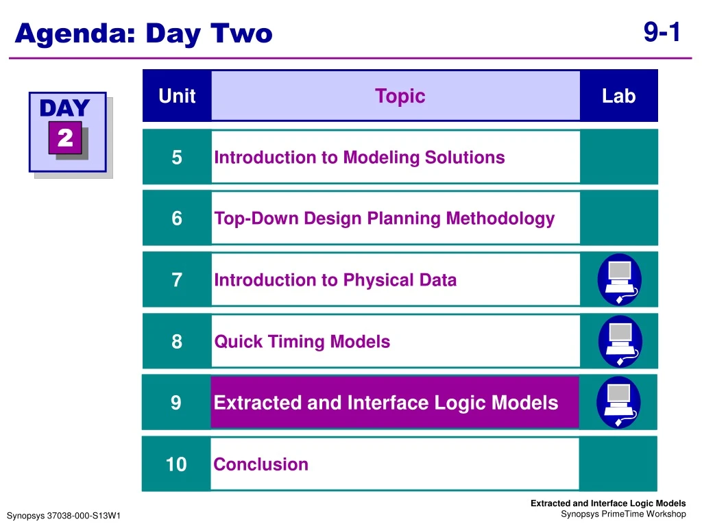
Agenda: Day Two. Topic. Unit. Lab. DAY. 2. Introduction to Modeling Solutions. 5. Top-Down Design Planning Methodology. 6. Introduction to Physical Data. 7. Quick Timing Models. 8. Extracted and Interface Logic Models. 9. Conclusion. 10. Unit Objectives.

E N D
Agenda: Day Two Topic Unit Lab DAY 2 Introduction to Modeling Solutions 5 Top-Down Design Planning Methodology 6 Introduction to Physical Data 7 Quick Timing Models 8 Extracted and Interface Logic Models 9 Conclusion 10
Unit Objectives • Create an Interface Logic Model, given a clean gate-level netlist • Extract a timing model, given a clean gate-level netlist • Execute two PT commands to compare interface timing between original gate-level netlist and the created model After completing this unit, you should be able to:
Recall RTL Planning RTL Planning Question How do I create ILMs? Top-Level Floorplan & Routing Design Planning Top-Level Netlist Physical Data Block-LevelExploratory Netlist or ILM PrimeTime Top-LevelIntegration DesignCompiler RTL & Internal Constraints Block-Level Synthesis Block-LevelPlace & Route Gate-Level Planning
Recall Gate-Level Planning Gate-Level Planning Top-Level Floorplan & Routing Design Planning Question How do I create extracted models? Top-Level Netlist Physical Data Block-LevelFinal Netlist, ILM or ETM PrimeTime Top-LevelIntegration DesignCompiler Netlist & Internal Constraints Block-Level Synthesis Block-LevelPlace & Route Sign-Off
Use Hierarchical STA • Static verification alone is hitting a bottleneck in capacity and runtimes as chip sizes continue to grow • To better handle today’s large and complex designs, STA must adopt a bottom-up approach through modeling • Reduce the runtime and memory image for full-chip analysis by replacing subblocks with models
Create an Interface Logic Model Create an Interface Logic Model Extract a Timing Model Validation of both ETMs and ILMs
Benefits of ILMs New in v2000.11 • Useful when • You wish to perform hierarchical STA in PrimeTime • You want a highly accurate model of subblocks which is accurate for any environment, drive or loading • You want an easy and fast solution which can be created multiple times during design flow
Recall ILMs: Graphically • Original gate-level netlist Can be converted to E Y O A P M B Z Q C N D E Y O A • Remove all internal register to register paths leaving only the interface netlist M B Z Q C N D
What Is an ILM? • An ILM is a flat gate-level Verilog netlist • Original netlist replaced by interface logic netlist • I/O logic and clock tree feeding this logic is preserved • Internal (register-to-register paths) logic is discarded • An ILM is created from an existing gate-level netlist Write Netlist, Script & Annotation for ILM Read & link block level design Constrain and annotate block level design Identify Interface Logic
Checklist: Before Creating an ILM • Fully constrain the design, for example: • Set environment attributes (operating conditions, wireload models, driving cell, load) • Define all clocks in the current_design, including generated clocks • Identify all timing exceptions • Do not constrain the design for a specific mode • Timing paths with disabled timing arcs will not be included in the ILM • Verify all paths are constrained • check_timing • Verify there are no violations • This is recommended but not mandatory • report_analysis_coverage
A X Y B CLK Step 1: Identify Interface Logic • Use identify_interface_logic to tag all interface logic in the current_design • This is the first ILM command to be used • Automatically ignores any path from an input port which has a fanout to more than 25% of total register count Attribute “is_interface_logic_pin” is set to true on interface logic pins
BlockA Flattened I2 I1 U2/FF1 U2/FF3 Verilog Netlist BlockA_ILM.v Step 2: Write ILM Flat Verilog Netlist • Use write_ilm_netlist to write netlist • Include all nets and pins in interface logic fanout that will effect delay calculations • These are additional pins not tagged in step 1 • This does not include pins on ideal nets, i.e. ideal prelayout clocks write_ilm_netlist -include_all_net_pins \ -verbose BlockA_ILM.v; # example in notes BlockA U2 I2 I1 FF2 FF1 FF3 FF4 U2/I3 I3 BlockA.v
Step 3: Write Constraints • Use write_ilm_script to capture assertions and exceptions which are valid for top-level integration and analysis write_ilm_script -instance I_BlockA_ILM.pt Write constraints to be used during top-level integration • Use write_ilm_script to capture assertions and exceptions which are used for model validation write_ilm_script BlockA_ILM.pt
Example: ILM Prelayout # Read original gate-level netlist read_verilog ADDSUB.v link_design # Fully constrain design source ./scripts/constraints/ADDSUB.tcl # Verify all paths are constrained and meet timing redirect ADDSUB.rpt check_timing redirect ADDSUB.rpt \ “report_analysis_coverage” -append # Create an ILM netlist and script file identify_interface_logic write_ilm_netlist -include_all_net_pins -verbose \ ILM_ADDSUB.v write_ilm_script -instance ILM_I_ADDSUB.pt write_ilm_script ILM_ADDSUB.pt; # for ILM validation
Create an ILM Postlayout • Everything is the same except before creating an ILM: • Read in physical data: SDF and parasitics • This is so you can subsequently write out a partial SDF and parasitic file only for the nets and cells in the ILM • Ensure you have propagated all real clocks in the design • This is so that PT will keep the clock tree information in the ILM • After creating the ILM, write out the partial parasitic files write_ilm_sdf BlockA.sdf write_ilm_parasitics-input_ports BlockA.spef Keep boundary net parasitic segments
Example: ILM Postlayout # Read original gate-level netlist read_verilog ADDSUB.v; link_design # Fully constrain design and read physical data source ./scripts/constraints/ADDSUB.tcl read_sdf ADDSUB.sdf read_parasitics ADDSUB.spef set_propagated_clock [all_clocks] # Verify all paths are constrained and meet timing redirect ADDSUB.rpt {check_timing; report_analysis_coverage} # Create an ILM netlist and script file identify_interface_logic write_ilm_netlist -include_all_net_pins -verbose \ ILM_ADDSUB.v write_ilm_script -instance ILM_I_ADDSUB.pt write_ilm_sdf ILM_ADDSUB.sdf write_ilm_parasitics -input_port ILM_ADDSUB.spef
Using an ILM During Top-Level STA # Read top-level and ILM gate-level netlist read_verilog “TOP.v ILM_ADDSUB.v”; link_design TOP # Apply top-level constraints and ILM constraints source TOP.pt current_instance I_ADDSUB source ILM_I_ADDSUB.pt current_instance # Apply physical data read_sdf TOP.sdf read_sdf -path I_ADDSUB ILM_ADDSUB.sdf read_parasitics TOP.spef read_parasitics -increment -path I_ADDSUB \ ILM_ADDSUB.spef # Perform top-level analysis!
Extract a Timing Model Create an Interface Logic Model Extract a Timing Model Validation of both ETMs and ILMs
Benefits of ETMs • Useful when: • You want to create a timing model for use in further design runs • Using Design Compiler, ChipArchitect/FlexRoute, or PT • A subblock is frozen or mostly completed • Model will be created once but used many times • You want to hide implementation details, i.e. IP
Recall ETMs Graphically Gate-level Netlist My_Design My_Design My_Design_core I1 O1 I2 O2 I3 O3 O4 CK O5 Extracted Model
What Is an Extracted Model? • An ETM is a black box static timing model • Internal register to register paths are not included in model • No internal pins except generated or internally defined clocks • An ETM is created from an existing gate-level netlist: • Timing is now gate-level accurate • The timing arcs are stored in a non-linear, 2D table • The timing arc delays are a function of input transition and capacitive loading
Checklist: Before Creating an ETM • Fully constrain the design, for example: • Set environment attributes (operating conditions, wireload models, driving cell, load) • Define all clocks in the current design, including generated clocks • Identify all timing exceptions • Do not constrain the design for a specific mode • Timing paths with disabled timing arcs will not be included in the ETM • Verify all paths are constrained • check_timing • Verify that there are no violations • This is recommended but not mandatory • report_analysis_coverage
Example: ETM Prelayout # Read gate-level netlist to be extracted read_verilog ADDSUB.v link_design # Fully constrain design source ./scripts/constraints/ADDSUB.tcl # Make sure all paths are constrained redirect ADDSUB.rpt check_timing # Make sure all paths are meeting constraints redirect ADDSUB.rpt \ “report_analysis_coverage” -append # Extract a timing model extract_model -output ETM_ADDSUB
ETM_ADDSUB.db ETM_ADDSUB_lib.db Using ETMs • The command extract_model will write out two “.db” files: • modelname.db -- contains the model netlist which instantiates a lower-level block called “core” • modelname_lib.db -- contains the actual timing specification extract_model myDesign Netlist PrimeTime Add to link_path variable
ETM_ADDSUB.db ETM_ADDSUB_lib.db Design Netlist Example ADDSUB core add_subN / Y 4 / A 4 carry_borrow B / 4 Clk ADDSUB_ core
Creating an ETM Postlayout • If you wish to extract a timing model using a fully back-annotated gate-level netlist: • Use only SPEF/DSPF/RSPF data • Using SDF causes the ETM to be context dependent • Remove any SDF data using remove_sdf • Use the most current version of PrimeTime • Boundary net parasitic data will be captured in an incremental SPEF or DSPF format • During top-level integration use read_parasitics -increment -path
Example: ETM Postlayout # Read gate-level netlist to be extracted read_verilog ADDSUB.v link_design # Fully constrain design and back-annotate # parasitic data. Make sure clocks are propagated! source ./scripts/constraints/ADDSUB.tcl read_parasitics ADDSUB.spef # make sure all paths are constrained and passing redirect ADDSUB.rpt check_timing redirect ADDSUB.rpt \ “report_analysis_coverage” -append # Extract a timing model along with incremental SPEF # for boundary nets extract_model -parasitic_format spef \ -output ETM_ADDSUB
Validation of Both ILMs and ETMs Create an Interface Logic Model Extract a Timing Model Validation of Both ILMs and ETMs
Two Commands for Model Verification New in v2001.06 ILM or ETM Original Netlist Model Generation write_interface_timing Interface Timing Report file Interface Timing Report file compare_interface_timing Comparison Report
The Command write_interface_timing • The command write_interface_timing creates a timing file for a gate-level netlist, an ILM or ETM. This file contains: • Worst case slack for all interface paths for min/ max/rise/fall • Actual transition times at each port for min/max/rise/fall • Total and effective capacitance at each port • Design rules at each port • Fully constrain the design for both setup and hold before executing this command pt_shell> read_db ETM_ADDSUB.db; link_design pt_shell> source ADDSUB.pt pt_shell> check_timing; report_analysis_coverage pt_shell> write_interface_timing ETM_ADDSUB.txt
The Command compare_interface_timing • The command compare_interface_timing compares two interface timing reports • Specify a slack and capacitance tolerance if appropriate • The results can be redirected to a file pt_shell> compare_interface_timing -slack_tol 0.1 \ -output compare.txt ETM_ADDSUB.txt ADDSUB.txt
Summary • ILMs offer high accuracy, fast model generation with moderate runtime improvements • ETMs offer huge runtime improvements with reasonable accuracy and moderate model generation times
Unit Review • Create an Interface Logic Model, given a clean gate-level netlist • Extract a timing model, given a clean gate-level netlist • Execute two PT commands to compare interface timing between original gate-level netlist and the created model
LAB Lab Overview • Create an extracted timing model from a clean gate-level netlist • Create an interface logic model from a clean gate-level netlist • Validate your models 60 minutes