Vehicle dynamics simulation using bond graphs
Vehicle dynamics simulation using bond graphs. Germán Filippini, Norberto Nigro and Sergio Junco Facultad de Ciencias Exactas, Ingeniería y Agrimensura Universidad Nacional de Rosario. Av. Pellegrini 250, S2000EKE Rosario, Argentina. Vehicle Chassis Engine and Transmission Pneumatic tires

Vehicle dynamics simulation using bond graphs
E N D
Presentation Transcript
Vehicle dynamics simulation using bond graphs Germán Filippini, Norberto Nigro and Sergio Junco Facultad de Ciencias Exactas, Ingenieríay AgrimensuraUniversidad Nacional de Rosario. Av. Pellegrini 250, S2000EKE Rosario, Argentina
Vehicle Chassis Engine and Transmission Pneumatic tires Suspensions Aerodynamic forces (4) z Bs Ks (3) yaw Ks Bs Kt roll y (2) pitch Kt Bs x r1 Ks (1) Ks ω Bs Kt h1 Kt Fy δ Fx Generalities and Modeling Assumptions
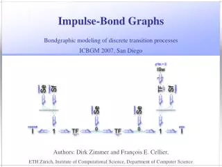
Mathematical and BG Modeling Rigid Body Euler equations Conservation of linear momentum Conservation of angular momentum
Mathematical and BG Modeling Power variables transformation between two points ‘A’, ‘B’ Equations relating the linear and rotational efforts Equations relating the linear and rotational flows
Mathematical and BG Modeling 3-dimensional rotation equations expressed in terms of power variables Euler angles Where,
Mathematical and BG Modeling Vehicle Chassis
Mathematical and BG Modeling • Engine and Transmission , Ap accelerator position Tpengine output torque Tr engine resistant torque
Mathematical and BG Modeling • Gearbox and Differential ,
Mathematical and BG Modeling • Pneumatic Tire Pacejka model Adherence coefficient Lateral force , with -1< <1the longitudinal slip
Mathematical and BG Modeling • Pneumatic Tire ,
Mathematical and BG Modeling • Suspension ,
Mathematical and BG Modeling • Aerodynamic forces , ρ air density Cx drag coefficient Af vehicle frontal area V relative velocity between the vehicle and the wind
Mathematical and BG Modeling • Full Vehicle vectorBG Model ,
Simulation Data • Renault Clio RL 1.1 Aerodynamics coefficient 0.33 Frontal area 1.86 m2 Distance between axes 2.472 m Vehicle weight 8100 N Centre of mass height 0.6 m Front axis weight 5100 N Rear axis weight 3000 N Maximum engine torque 78.5 Nm at 2500 rpm Maximum engine power 48 CV at 5250 rpm Planetary drive train (differential) ratio 3.571 First gearbox ratio 3.731 Second gearbox ratio 2.049 Third gearbox ratio 1.321 Four gearbox ratio 0.967 Five gearbox ratio 0.795 Reverse gearbox ratio 3.571 Tires, type and dimensions 145 70 R13 S Wheelbase 1.650 m Maximum speed 146 km/h Acceleration 0-100 km/h in 17 s Time spent to do 1000 meters 38 s Distance from centre of mass to front axes 0.916 m Distance from centre of mass to rear axes 1.556 m Pneumatic tire radius (unloaded) 0.2666 m Air density 1.225 kg/m3 Unsprung masses (at each wheel) 38.42 kg Tire Vertical stiffness 150 000 N/m Tire inertia 1.95 Kgm2 Damper coefficient 475 N s / m Suspension stiffness 14 900 N/m Sprung mass - Yaw Inertia 2345.53Kg m2 Sprung mass - Pitch Inertia 2443.26Kg m2 Sprung mass - Roll Inertia 637.26 Kg m2 ,
Simulation Results • First Test Time evolution of the engine speed. Evolution of the load [N] over a traction wheel. , Longitudinal vehicle velocity [m/s] in time. Chassis pitching as a function of time. Evolution of one of the traction wheels sliding. Load [N] over one of the rear wheels.
Simulation Results • Second Test Sliding angle of one of the front wheels. , Evolution of the turning angle [rad] of the front wheels. . Sliding angle of one of the rear wheels as a function of time. Trajectory in x-y [m] Yaw vehicle response as a function of time.
Simulation Results • Third Test Slip angle of one of the front wheels [rad] , Evolution of the turning angle [rad] of the front wheels. . Slip angle of one of the rear wheels [rad]. Trajectory x-y [m] Yaw angle [rad] as a function of time.
Conclusions • One of the main goals of this paper was the extension of this formalism to include large spatial (3-dimensional) rotations. • Several elements oriented to multibody systems were developed allowing work with different reference frames, operating with them through the usage of translations and general transformations. • This toolbox works acceptable in the vehicle dynamics prediction and it was successfully applied to another project based on vehicle fault diagnostics.