
Observation of Femtosecond Bunch Length Using a Transversely Deflecting RF Structure
This study presents the implementation of a transverse deflecting RF structure (LOLA) at DESY, critical for the design of the VUV-FEL, which requires bunch lengths of 50 fs and below. The RF deflector allows for the analysis of the beam's longitudinal profile by streaking it according to the distribution. Tests revealed a pronounced substructure in the bunch, achieving an RMS length of approximately 50 fs during operation and below 20 fs FWHM at maximum compression. Additionally, resolutions below 50 fs have been successfully reached, providing valuable insights into these ultrashort bunches.

Observation of Femtosecond Bunch Length Using a Transversely Deflecting RF Structure
E N D
Presentation Transcript
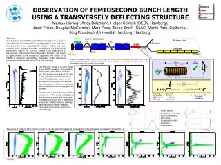
RF ‘streak’ V(t) 3.66 m sy bp e- transverse RF deflector Dyy bc sz sz 25 mm Dyy 15.8 E0 0.6 GeV j 0 (bcbp)1/2 51 m l 105 mm gey 5 mm sy0 317 mm L 3.66 m, V0 25 MV, P0 18 MW sy 925 mm OBSERVATION OF FEMTOSECOND BUNCH LENGTH USING A TRANSVERSELY DEFLECTING STRUCTUREMarkus Hüning*, Andy Bolzmann, Holger Schlarb (DESY, Hamburg),Josef Frisch, Douglas McCormick, Marc Ross, Tonee Smith (SLAC, Menlo Park, California),Jörg Rossbach (Universität Hamburg, Hamburg) Laser Abstract The design of the VUV-FEL at DESY demands bunch lengths in the order of 50 fs and below. For the diagnostic of such very short bunches a transverse deflecting RF structure (LOLA) has been installed which streaks the beam according to the longitudinal distribution. Tests in the VUV-FEL yielded a rich substructure of the bunches. The most pronounced peak in the has a rms length of approximately 50 fs during FEL operation and below 20 fs FWHM at maximum compression. Depending on the transverse focusing a resolution well below 50 fs was achieved. Bunch Compressor #1 #2 • By-Pass Line • Collimator • Undulator • Dump LOLA Screen CTR RF-Gun Figure 1: Schematic drawing of the VUV-FEL beam line. At the end of the accelerating section there is the transversely deflecting structure LOLA. It streaks the beam vertically so that on a downstream viewscreen the longitudinal profile of the bunches can be studied. Left and right: Image of a LOLA streak during SASE operation. The streak is vertical, the head of the bunch is on top. The streak was 4 fs/pixel (26 mm). During standard operation the beam size at the diagnostic screen is not optimized for minimum vertical beam size. Although in a different regime the two settings delivered comparable FEL intensity. Far right: LOLA streak during dedicated machine time. The streak was 2fs/pixel, and the vertical beam size minimized, indicated by the blue line. The settings were close to FEL operation, but may have deviated in certain respects. Especially compression might have been stronger. Phase space simulation of the first bunch compressor. Left: weak compression, right: maximum compression. Sequence of stepping ACC1 from on-crest to 12° off-crest, the maximum compression in the first bunch-compressor is found at 14° THPP035


