Download
1 / 29
300 likes | 400 Views
HYDRAULIC FRACTURING. DESCRIPTION OF HYDRAULIC FRACTURING ( FRACKING )

E N D
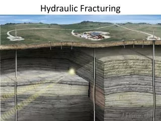
HYDRAULIC FRACTURING DESCRIPTION OF HYDRAULIC FRACTURING (FRACKING) The operation entails using special pump/compressor pipes to pump highly viscous fluid (gel) based on water or hydrocarbons (petroleum, diesel fuel) into the well. The pressure created by the fluid fractures the formation along minimum stress planes of overburden pressure. As a result, a fracture forms in the formation. After fracking the fracture keeps growing as more fluid is pumped into the well. When the fracture grows to a particular size, propping agent (proppant) is fed into the fracking fluid (artificial bauxite sand with spherical particles). The fluid takes the proppant to the fracture. The proppant must hold the fracture open when the pumping stops and the overpressure is withdrawn. At the final stage the gel pushes the proppant, which remains in the well after filling the fracture, into the formation. In this way, by creating a proppant-filled fracture, formation volume drained by the well is expanded, previously untapped deposits are connected, and a high-throughput channel is formed to deliver oil into the well. This allows to increase the flow rate of the well several-fold (average increase for oil is 3-fold), increase the recovery ratio of the formation thus turning a part of non-commercial OIP into commercial oil reserves.
RUSSIAN HYDRAULIC FRACTURING SPREAD FOR OIL AND GAS FORMATIONS
HYDROFRACKING SPREAD LAYOUT DIAGRAM 1 – SKU-10; 2 – UN-2250; 3 – US-10; 4 – BM-105; 5 – MM-105; 6 – gel tank; 7 – proppant bunker.
HYDRAULIC FRACTURING SPREAD AUTOMATED CONTROL AND MONITORING SYSTEM • The spread facilitates automated (computerized) control of the hydrofracturing process under oversight of the operations manager, the engineer, and the operator of the UN-2250pumping unit, who are present at the SKU-10 monitoring and control station. It also enables visual monitoring of fracking parameters on three monitors and the main control panel of the SKU-10station, as well as on the US-10 blender. • Hydrofracking process parameters can be adjusted manually throughout the process; it is also possible to switch to manual control completely. • Components of hydrofracturing process control and monitoring (incl. visual) of fracking parameters are combined into the SAUK automated control and monitoring system, including: • System software • 2 industrial computers of the SKU-10 station • Three monitors of the SKU-10 station • Common control panel for pumping units in the SKU-10 station • Printer of the SKU-10 station • 1 industrial computer of the US-10 blender • Coupling hardware unit of the US-10 blender • Control and monitoring panel with a monitor and manual controls of the US-10 blender
SKU-10 MONITORING AND CONTROL STATION The SKU-10 monitoring and control station automatically controls the UN-2250 (UN) pumping units and the US-10 blender as part of hydraulic fracturing of oil and gas formations. It maintains, as specified by industrial computer software or the operator, set points for working fluid and dry and liquid chemicals, and proppant concentration. It also monitors and logs parameters (direct and calculated), archives behavior and operating parameters of the spread, and logs behavior and operating parameters on paper media. Climatic category “U1” (temperate climate, outdoors) GOST 15150-69.
SKU-10 MONITORING AND CONTROL STATION TECHNICAL DETAILS TECHNICAL DETAILS
COMPONENTS AND EQUIPMENT OF SKU-10 Cabinet withfume hood Rack with computingequipment Air conditioner Common control panelof the UN Laboratory chemist Supervisor Process engineer Operationsmanager UN operator
COMPONENTS AND EQUIPMENT OF SKU-10 Diesel generator Cable reels Coupling socketboard
SKU-10 MONITORING AND CONTROL STATION SCHEDULE OF MONITORED AND LOGGED PARAMETERS OF THE FRACKING PROCESS • Time and pressure parameters • - Date, time, Customer, Contractor, field, well, planned fracking parameters. • - Pumping pressure 1 (BM-105), mPa. (max 85mPa) • - Pumping pressure 2 (UN-2250), mPa (max 85 mPa) • Casing pressure, mPa (max 20 mPa) • Mixture flow rate and totalizers • - Flow 1 at US mixer outlet, m3/min (max 15 m3/min) • - Flow 2 at US mixer outlet, m3/min (max 15 m3/min) • - Flow 3 at UN No. 1...4 pumping unit tachometers, m3/min (max 15 m3/min) • - Mixture totalizer for flow 1 at outlet, m3 • - Mixture totalizer for flow 2 at outlet, m3 • Mixture totalizer for flow 3 at tachometers, m3 • Pure fluid flow and totalizers • - Flow 1 at US inlet, m3/min • - Flow 2 at US inlet, m3/min • - Pure flow totalizer for flow 1 at US-10 inlet, m3 • - Pure flow totalizer for flow 2 at US-10 inlet, m3 • - Total volume of pumped pure fluid from tanks, m3 • Proppantconcentration and totalizers • - Proppant concentration 1 (acc. to density meter), kg/m3 • - Proppant concentration 2, kg/m3 • - Proppant totalizer 1, kg • - Proppant totalizer 2, kg • - Proppant totalizer 3, kg • Proppantdelivery rate deriv. from rpm, screw conveyor 1 • kg/min • - Proppant delivery rate deriv. from rpm, screw conveyor 2 kg/min • - Proppant delivery rate deriv. from rpm, screw conveyor 3 kg/min • - Proppant totalizer, deriv. from rpm of screw conveyors 1, 2, 3 kg • - Total mass of pumped proppant, kg • Concentration of liquid and dry additives and totalizers • - Flow rate of liquid additive 1, l/min • - Flow rate of liquid additive 2, l/min • - Totalizer for liquid additive 1, l • - Totalizer for liquid additive 2, l • - Delivery rate of dry additive. Screw conveyor 1, kg/min • - Delivery rate of dry additive. Screw conveyor 2, kg/min • - Totalizer for dry additive. Screw conveyor 1, kg • - Totalizer for dry additive. Screw conveyor 2, kg • - Total mass of pumped dry additive, kg
SKU-10 SOFTWARE MONITORING AND DIAGNOSTICS OF HYDROFRACKING PROCESS
SKU-10 SOFTWARE RAW DATA INPUT GRAPHICAL REPRESENTATION OF HYDROFRACKING REPORT GENERATION
UN-2250 PUMPING UNIT • The UN-2250 pumping unit is designed for the pumping of working fluid or working fluid–proppant mixtures into the well under pressure and with performance sufficient for hydraulic fracturing of deposits, and to effect hydraulic, sand jet, or chemical treatment of bottom-hole area at oil and gas fields. Climatic category “U1” (temperate climate, outdoors) GOST 15150-69. • The UN-2250 provides the following functionality: • Automated hydrofracturingoperation • Automated transmission gear shifting without breaking the power path and managing gas turbine engine operating modes. • The common control panel allows smooth adjustment of SKU test pressure for manifolds and pump/compressor pipes, created by the UN in the 0...85 MPa range. • 0...2.5 m3/min smooth adjustment range of UN pumping rate at the common control panel on the SKU. • Automatic maintenance of constant pumping rate (regardless of the differential pressure caused by the well) on command from the common control panel to the SKU. • Automated integrated monitoring of UN units and systems. • Halting the pumping of working fluid into the well if maximum well pressure protection is tripped, without stopping the gas turbines.
UN-2250 PUMPING UNIT TECHNICAL DETAILS
UN-2250 PUMPING UNIT PERFORMANCE DIAGRAM The diagram shows flow rates, at which the automated operating modes control system shifts gears of KP1 and KP2
EQUIPMENT OF THE UN-2250 PUMPING UNIT GTD-1250gas turbine engines NTP-2250 pump Fuel tank Automatictransmission Enginecontrol drive Tank of the NTP-2250 power endlubrication system
EQUIPMENT OF THE UN-2250 PUMPING UNIT Air system tanks Coupling Rechargeablebatteries Engine startupequipment Plunger seal lubrication system
REMOTE CONTROL PANEL OF THE UN-2250 Operational monitoringof systems Switching of processmodes Switching of control modes Monitoring of operating parameters Automatic overpressureprotection Automated flow set point maintenance
NTP-2250 PLUNGER PUMP Maximum power: 2250 h.p.
US-10 BLENDER The Mixing Unit is designed for preparing working fluids and mixtures as part of mobile systems for hydraulic fracturing and delivery of fluids and mixtures to the UN unit during hydraulic conditioning of the well bore area at oil fields. The Mixing unit allows: - Automated operation in fluid, mixture preparation modes and hydrofracturing mode - Preparation of working fluids and mixtures using guar gum powder, activators, thickeners, clay stabilizers, demulsifiers, crosslinkers, bulk chemicals, breakers, proppants - Adjustable supply of liquid chemicals when preparing working fluids and delivering fluids and mixtures to the UN during hydrofracturing - Adjustable supply of breaker and proppant to the ingress bunker of the mixer during hydrofracturing.
US-10 BLENDER TECHNICAL DETAILS
COMPONENTS AND EQUIPMENT OF US-10 Diesel drive Liquid additive tanks Liquid additiveflow meters Mixer Proppant deliverymechanism Aspirator pump Controlled-volume pumps
COMPONENTS AND EQUIPMENT OF US-10 Dry additive introduction mechanism Densitymeter Electromagneticflow meter Turbineflow meter Force pump
US-10 CONTROL SYSTEM • The US-10 operation control system automatically provides: • Scheduled flow of working fluids (mixtures) during preparation and hydrofracturing • Scheduled flow of liquid additives during fluid and mixture preparation and delivery to the UN unit • Scheduled introduction of dry additives (breakers) into fluids and mixtures during hydrofracturing • Scheduled proppant concentration in the mixture during hydrofracturing • Processing of instrument data and transmitting data to the SKU • If necessary, the operator may quickly switch to manual operation on the monitoring and control panel in the US cabin.
US-10 MONITORING AND CONTROL PANEL Hydraulic systemmonitoring Operating parametersdisplay Manualcontrolof processequipment YaMZ enginecontrol panel Valvecontrol Controlmodeswitch US electric equipmentcontrol