Download
1 / 58
580 likes | 729 Views
Simulating materials with atomic detail at IBM: From biophysical to high-tech applications. Application Team Glenn J. Martyna, Physical Sciences Division, IBM Research Dennis M. Newns, Physical Sciences Division, IBM Research

E N D
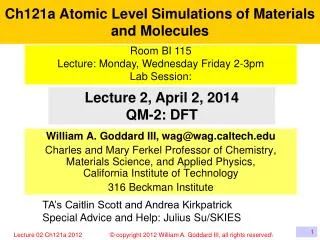
Simulating materials with atomic detail at IBM: From biophysical to high-tech applications Application Team Glenn J. Martyna, Physical Sciences Division, IBM Research Dennis M. Newns, Physical Sciences Division, IBM Research Jason Crain, School of Physics, Edinburgh University Andrew Jones, School of Physics, Edinburgh University Razvan Nistor, Physical Sciences Division, IBM Research Ahmed Maarouf, Physical Sciences Division, IBM Research and EGNC Marcelo Kuroda, Physical Sciences Division, IBM and CS, UIUC Methods/Software Development Team Glenn J. Martyna, Physical Sciences Division, IBM Research Mark E. Tuckerman, Department of Chemistry, NYU. Laxmikant Kale, Computer Science Department, UIUC Ramkumar Vadali, Computer Science Department, UIUC Sameer Kumar, Computer Science, IBM Research Eric Bohm, Computer Science Department, UIUC Abhinav Bhatele*, Computer Science Department, UIUC Ramprasad Venkataraman, Computer Science Department, UIUC *George Michael Memorial High Performance Computing Fellows for 2009 Funding : NSF, IBM Research, ONRL
IBM’s Blue Gene/L network torus supercomputer Our fancy apparatus.
Goal : The accurate treatment of complex heterogeneous systems to gain physical insight.
Characteristics of current models Empirical Models: Fixed charge, non-polarizable, pair dispersion. Ab Initio Models: GGA-DFT, Self interaction present, Dispersion absent.
Problems with current models (empirical) Dipole Polarizability : Including dipole polarizability changes solvation shells of ions and drives them to the surface. Higher Polarizabilities: Quadrupolar and octapolar polarizabilities are NOT SMALL. All Manybody Dispersion terms: Surface tensions and bulk properties determined using accurate pair potentials are incorrect. Surface tensions and bulk properties are both recovered using manybody dispersion and an accurate pair potential. An effective pair potential destroys surface properties but reproduces the bulk. Force fields cannot treat chemical reactions:
Problems with current models (DFT) • Incorrect treatment of self-interaction/exchange: • Errors in electron affinity, band gaps … • Incorrect treatment of correlation: Problematic • treatment of spin states. The ground state of transition metals (Ti, V, Co) and spin splitting in Ni are in error. Ni oxide incorrectly predicted to be metallic when magnetic long-range order is absent. • Incorrect treatment of dispersion : Both exchange • and correlation contribute. • KS states are NOT physical objects : The bands of the exact DFT are problematic. TDDFT with a frequency • dependent functional (exact) is required to treat • excitations even within the Born-Oppenheimer approximation.
Conclusion : Current Models • Simulations are likely to provide semi-quantitative accuracy/agreement with experiment. • Simulations are best used to obtain insight and examine physics .e.g. to promote understanding. Nonetheless, in order to provide truthful solutions of the models, simulations must be performed to long time scales!
Limitations of ab initio MD (despite our efforts/improvements!) • Limited to small systems (100-1000 atoms)*. • Limited to short time dynamics and/or sampling times. • Parallel scaling only achieved for • # processors <= # electronic states • until recent efforts by ourselves and others. • Improving this will allow us to sample longer and learn new physics. *The methodology employed herein scales as O(N3) with system size due to the orthogonality constraint, only.
Solution: Fine grained parallelization of CPAIMD. Scale small systems to 105 processors!! Study long time scale phenomena!! (The charm++ QM/MM application is work in progress.)
IBM’s Blue Gene/L network torus supercomputer The worlds fastest supercomputer! Its low power architecture requires fine grain parallel algorithms/software to achieve optimal performance.
Electronic states/orbitals of water Removed by introducing a non-local electron-ion interaction.
Plane Wave Basis Set: The # of states/orbital ~ N where N is # of atoms. The # of pts in g-space ~N.
Plane Wave Basis Set: Two Spherical cutoffs in G-space n(g) gz gz y(g) gy gy gx gx n(g) : radius 2gcut y(g) : radius gcut g-space is a discrete regular grid due to finite size of system!!
Plane Wave Basis Set: The dense discrete real space mesh. n(r) z z y(r) y y x x n(r) = Sk|yk(r)|2 n(g) = 3D-IFFT{n(r)} exactly! y(r) = 3D-FFT{ y(g)} Although r-space is a discrete dense mesh, n(g) is generated exactly!
Simple Flow Chart : Scalar Ops Memory penalty Object : Comp : Mem States : N2 log N : N2 Density : N log N : N Orthonormality : N3 : N2.33
Parallelization under charm++ Transpose Transpose Transpose Transpose Transpose RhoR
Effective Parallel Strategy: • The problem must be finely discretized. • The discretizations must be deftly chosen to • Minimize the communication between processors. • Maximize the computational load on the processors. • NOTE , PROCESSOR AND DISCRETIZATION ARE • SEPARATE CONCEPTS!!!!
Ineffective Parallel Strategy • The discretization size is controlled by the number of physical processors. • The size of data to be communicated at a given step is controlled by the number of physical processors. • For the above paradigm : • Parallel scaling is limited to # processors=coarse grained parameter in the model. • THIS APPROACH IS TOO LIMITED TO ACHIEVE FINE GRAINED PARALLEL SCALING.
Virtualization and Charm++ • Discretize the problem into a large number of very fine grained parts. • Each discretization is associated with some amount of computational work and communication. • Each discretization is assigned to a light weight thread or a ``virtual processor'' (VP). • VPs are rolled into and out of physical processors as physical processors become available (Interleaving!) • Mapping of VPs to processors can be changed easily. • The Charm++ middleware provides the data structures and controls required to choreograph this complex dance.
Parallelization by over partitioning of parallel objects : The charm++ middleware choreography! Decomposition of work Charm++ middleware maps work to processors dynamically Available Processors On a torus architecture, load balance is not enough! The choreography must be ``topologically aware’’.
Challenges to scaling: • Multiple concurrent 3D-FFTs to generate the states in real space require AllToAll communication patterns. Communicate N2 data pts. • Reduction of states (~N2 data pts) to the density (~N data pts) in real space. • Multicast of the KS potential computed from the density (~N pts) back to the states in real space (~N copies to make N2 data). • Applying the orthogonality constraint requires N3 operations. • Mapping the chare arrays/VPs to BG/L processors in a topologically aware fashion. Scaling bottlenecks due to non-local and local electron-ion interactions removed by the introduction of new methods!
Topologically aware mapping for CPAIMD Density N1/12 States ~N1/2 Gspace ~N1/2 (~N1/3) • The states are confined to rectangular prisms cut from the torus to • minimize 3D-FFT communication. • The density placement is optimized to reduced its 3D-FFT communication and the multicast/reduction operations.
Topologically aware mapping for CPAIMD : Details Distinguished Paper Award at Euro-Par 2009
Improvements wrought by topological aware mappingon the network torus architecture Density (R) reduction and multicast to State (R) improved. State (G) communication to/from orthogonality chares improved.‘’Operator calculus for parallel computing”, Martyna and Deng (2009) in preparation.
Parallel scaling of liquid water* as a function of system size on the Blue Gene/L installation at YKT: *Liquid water has 4 states per molecule. • Weak scaling is observed! • Strong scaling on processor numbers up to ~60x the number of states!
Software : Summary • Fine grained parallelizationof the Car-Parrinello ab initio MD method demonstrated on thousands of processors : • # processors >> # electronic states. • Long time simulations of small systems are now possible on large massively parallel supercomputers.
Instance parallelization • Many simulation types require fairly uncoupled instances of existing chare arrays. • Simulation types is this class include: 1) Path Integral MD (PIMD) for nuclear quantum effects. 2) k-point sampling for metallic systems. 3) Spin DFT for magnetic systems. 4) Replica exchange for improved atomic phase space sampling. • A full combination of all 4 simulation is both physical and interesting
Replica Exchange : M classical subsystems each at a different temperature acting indepently Replica exchange uber index active for all chares. Nearest neighbor communication required to exchange temperatures and energies
PIMD : P classical subsystems connect by harmonic bonds Classical particle Quantum particle PIMD uber index active for all chares. Uber communication required to compute harmonic interactions
K-points : N-states are replicated and given a different phase. k0 k1 Atoms are assumed to be part of a periodic structure andare shared between the k-points (crystal momenta). The k-point uber index is not active for atoms and electron density. Uber reduction communication require to form the e-density and atom forces.
Spin DFT : States and electron density are given a spin-up and spin-down index. Spin up Spin dn The spin uber index is not active for atoms. Uber reduction communication require to form the atom forces
``Uber’’ charm++ indices • Chare arrays in OpenAtom now posses 4 uber ``instance’’ indices. • Appropriate section reductions and broadcasts across the ‘’Ubers’’ have been enabled. • We expect full results for July 2010.
Goal : The accurate treatment of complex heterogeneous systems to gain physical insight.
Transparent Conducting Electrodes (TCEs) for (inexpensive) amorphous silicon solar cells • Graphene TCEs: • 1 – 8 atomic layers • Conventional TCEs: • Indium Tin Oxide (ITO) • Zinc Oxide (ZnO) • Performance: • Transparency 95% • Sheet resistance 10W • Performance: • Transparency 85% • Sheet resistance 100W Manufacturing: Manufacturing: cm X cm size sheets Science, 324, p. 1312 (2009).
http://www.rsc.org/ Graphene – single atomic layer of carbon Chemical Doping: Transparent – 2% loss per layer High Mobility – 2 x 10⁵ (cm2 / Vs)
Goal Engineering goal # layers Experimental collaborators G. Tulevski (IBM), A. Kasry (EGNC), A. Boll (IBM)
aSi + Graphene on BG/L • Plane wave based DFT CODES: • OpenAtom • Quantum Espresso • Abinit PZ functional 800 eV (60 Ry.) Ecut 100ps quench aSi 10ps relaxation Graphene + intercalates: Explore various n and p dopants on layers Orientation of Layers – Marcelo, Ahmed talks Graphene + substrate: Explore interface and transport from semiconducting layer to graphene Entire system: Calculate electronic properties of entire +500 atom systems using full ab initio
0.2 eV 1% strain 0.1eV gap Graphene on aSi:H – Structural results Ideal single layer: Relaxed single layer: Relaxed multi layer: See also Zhen Hua Ni et al. ACS Nano, 2008, 2 (11), pp 2301
EFermi Graphene Intercalates Electron donors: Alkali group elements – Li, K Hole donors: HNO3 AlCl3, FeCl3, SbCl5
Graphene Intercalates – HNO3 EFermi
Graphene Intercalates – HNO3 EFermi No shift – no doping
Graphene Intercalates – HNO3 EFermi No shift – no doping
Graphene Intercalates – HNO3 HNO3 decomposition Graphene layers facilitate decomposition
Graphene Intercalates – HNO3 HNO3 decomposition (movie) - Top view with invisible graphene
Decomposition product - NO3 anion EFermi Old EFermi Integrate 1 hole per molecule
O2 O1 O3 s N p HNO3 decomposition products From graphene NO3- 1 / 3 1 / 3 1 / 3 e from graphene in oxygen p-orbitals See also: Wehling et. al, Nano Letters, 8, 173 (2008) Gierz et. al, Nano Letters, 8, 4603 (2008)