Download
1 / 36
360 likes | 483 Views
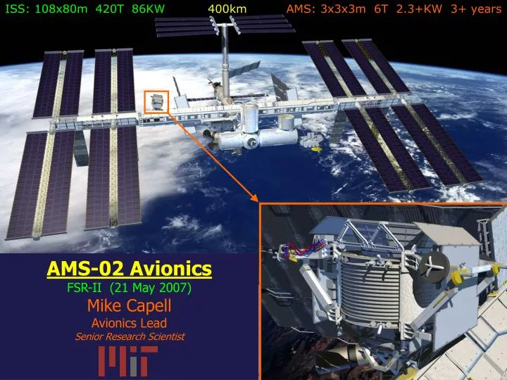
ISS: 108x80m 420T 86KW 400km AMS: 3x3x3m 6T 2.3+KW 3+ years. AMS-02 Avionics FSR-II (21 May 2007) Mike Capell Avionics Lead Senior Research Scientist. Subdetector Requirements: Summary. 7 Gbit/sec >> 2 Mbit/sec ⇒ Restrict Rate & Size.

E N D
ISS: 108x80m 420T 86KW 400kmAMS: 3x3x3m 6T 2.3+KW 3+ years AMS-02 Avionics FSR-II (21 May 2007) Mike Capell Avionics Lead Senior Research Scientist AMS-02 Electronics
Subdetector Requirements: Summary 7 Gbit/sec >> 2 Mbit/sec ⇒ Restrict Rate & Size Specify, design, develop, produce: High Speed, High Capacity, Low Power, Low Weight, Reliable Signal & Data Processing ON ORBIT ! AMS-02 Electronics
Data Acquisition & Trigger Scheme • Subdetector specific front ends (5 types, 1600 units) • Common DAQ nodes (1 type, 300 units) • General purpose computers with specialized interfaces (4x redundant) • Trigger system to meter data flow. Fast Level Level Trigger -1 -3 Signal Front End Intermed. Top Level Buffer & Digitization Detector Preperation DAQ DAQ DAQ Output AMS-02 Electronics
Subsystems AMS Power & Thermal TDRS Monitor & Control DAQ & Trigger EVA UMA International Space Station M&C Power HRDL LRDL Monitoring & Command EventData Electrical POCC Interfaces Earth NASA AMS Electrical Interfaces on ISS Power: 109-124VDC 2KW max LRDL 1553B Bus 1 Kbit/s in 10 Kbit/s out10 B/sec CHD HRDL Taxi F/O <2Mbit/s>orbit xRDL: Duty cycle ~50-70% Ensure AMS side of interfaces conform to NASA requirements AMS-02 Electronics
Electronics Designed for Low Earth Orbit • Challenges: • Static loads: 40+10+10g • Vibration: 6.8g rms • Depressurization: 1 to 0 atmosphere in 2 min. • 0 g & Vacuum: No convection, outgassing (evaporation) • Operational Range: -20 to +50 C operational • Ionizing Radiation: ~ 1 Krad/year • Heavy Ions (SEE): latch ups, bit flips • Atomic O, Solar UV: Etching & Aging • MM/OD(Space Junk): Impact • Electromag. Compat: with ISS, within AMS • AMS Magnetic Field: several hundred Gauss • NO ACCESS: 3+ years AMS-02 Electronics
Electronics Designed for Low Earth Orbit Challenges: Solutions: Static loads: Mechanical Design Vibration: Mechanical Design Depressurization: Mechanical Design 0 g & Vacuum: Materials, Thermal Management Operational Range: Components, Thermal Management Ionizing Radiation: Component Selection Heavy Ions (SEE): Comp Sel, Beam Tests, Protection Atomic O, Solar UV: Materials MM/OD(Space Junk): Mechanical Design Electromag. Compat: Shielding, Grounding AMS Magnetic Field: Selection & Test NO ACCESS: Redundancy, Reliability,TEST, TEST, TEST Process validated with AMS-01 electronics AMS-02 Electronics
AMS-01 Electronics: Qualification AMS-02 Electronics
AMS-01 Electronics: Typical board AMS-02 Electronics
Process to transform electronics from High Energy Physics for use in Low Earth Orbit Testing Models ComponentsPerformance, Beam Test functional EM + Vibration, Thermal Prototype QM1 Prototype + Thermal-Vacuum, EMC, Prod. Prototype QM2 FM, FS (==QM2) All (min level) AMS-02 Electronics
GSI Heavy Ion Beam Test Setup: Main Computer components CPC 700 Bridge PPC 750 CPU GSI Heavy Ion Accelerator Ion Beam Direction AMS-02 Electronics
AMS-02 Electronics Component Selection Reliability Thermal requirements (-40 to +85 C) test Space use heritage, fabrication process technology Single lot procurement & Screening Total dose (600 Rad/year) test Single Event Effects – Latch-ups & Upsets: test Design modified for some components for: retest Latch-up & Bit flip protection. AMS-02 Electronics
AMS Custom/Common Readout Unit Cust/Comm power supplies w/high efficiency. Cust/Comm monitor & control interfaces. Cust/Comm processing unit, software, links. DSP (ADSP-2187L), Gate Array (Actel A54SX-2A), SRAM (Samsung K6R-016V1C), Flash (AMD Am29LV004), LVDS Tx/Rx (TI SN65LVD-39-), etc. AMS-02 Electronics
Data Acquisition Tree(parallel, independent tree for trigger) 10 MB/s serial links x4 redundant AMS-02 Electronics
JT-Crate Connects about ~ 200 signal cables. AMS-02 Electronics
Data Reduction (UDR2, TDR2) Boards 70 types of boards 454 boards total Where to put them ? AMS-02 Electronics
Electronics Mechanics– Crates & Boxes on Radiators 1. Keep heat away from Magnet 2. Temp range of electronics >> detectors 3. Shortest path to radiators AMS-02 Electronics
Ram Radiator (~4m2) Electronics ~ 750W “xPD” 28VDC to LV “x-Crate” readout &monitoring Each type of box optimized for weight vs. thermal vs. structural performance.Design and test supported by NSPO, Taiwan x=E,J,S,T,TT,U,UG,… AMS-02 Electronics
Electronics Production & Quality Assurance • Designed by Academia Sinica, CSIST & MIT Adapted for particular subdetectors by Aachen, Geneva, Perugia, Bologna, Madrid, Annecy, Pisa, … • Most electronics produced at CSIST: High Reliability (Mil Spec) infrastructure, Qualification: Vibration, Thermal, EMC on site Team of 25 engineers and 40 technicians Quality assured by NASA & AMS team reviews every 3 months. • Testing & Qualification by board designers AMS-02 Electronics
Recent Board Tests at CSIST Daniel testing TDR2 (June) Sandor testing DCDC with Wang & Liu(June) Sylvie & Nadia testing EIB (July) Lucio testing TBS & TPSFE (July) Jesus & Antonio test DC-DC(July) AMS-02 Electronics
Thermal Stress Screening AMS-02 Electronics
J-Crate Scheme & test setup 4* Main Computer + Interfaces AMS-02 Electronics
J-Crate in Thermal Chamber Thermal Qualification Operating: -15, +60CNon-Oper: -40, +90 AMS-02 Electronics
J-Crate inside EMI Chamber AMS-02 Electronics
J-Crate in Thermal Vacuum Tests AMS-02 Electronics
Subsystems AMS Power & Thermal TDRS Monitor & Control DAQ & Trigger EVA UMA International Space Station M&C Power HRDL LRDL Monitoring & Command EventData Electrical POCC Interfaces Earth NASA AMS Electrical Interfaces on ISS Power: 109-124VDC 2KW max LRDL 1553B Bus 1 Kbit/s in 10 Kbit/s out10 B/sec CHD HRDL Taxi F/O <2Mbit/s>orbit xRDL: Duty cycle ~50-70% Ensure AMS side of interfaces conform to NASA requirements AMS-02 Electronics
AMS-02 HRDL Interface ISS is Zero Fault Tolerant for Payloads ROEU AMS-02 Electronics
Practicing EVA cable swap at in Neutral Buoyancy Lab AMS-02 Electronics
High Rate Data Link Data Flow AMS-02 Electronics
PIT: Preliminary Interface Test - JSC - Jun 2003 AMS-02 Electronics
ISIL Testing – July ’05 at JSC AMS-02 Electronics
AMS-02 Magnet & CryogenicsElectronics 4 types of Valves TMPs ΔT = 0.01K Many sensors Passive PhaseSeparatorΔT = 0.001K SFHe tank Vacuum vessel AMS-02 Electronics
2100W peak AMS-02 Electronics
Cryomagnet Current Source under test (460A) AMS-02 Electronics
AMS Electronics Adapted particle physics capabilities to work in low Earth orbit. Key steps Component selection & beam testing, Thermo-mechanical design, Quality assurance & Hi-rel processing, High Power (PDS), High Current(CAB) units produced by “space rated firms”, Continuous oversight/interaction with NASA/(Lockheed/LM/JS/Jacobs). AMS-02 Electronics