PWM Mode
PWM Mode. PWM Mode. In Pulse Width Modulation mode, the CCPx pin produces up to a 10-bit resolution PWM output. Since the CCP1 pin is multiplexed with the PORTC data latch, the TRISC<2> bit must be cleared to make the CCP1 pin an output


PWM Mode
E N D
Presentation Transcript
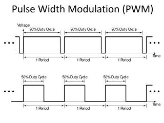
PWM Mode • In Pulse Width Modulation mode, the CCPx pin produces up to a 10-bit resolution PWM output. • Since the CCP1 pin is multiplexed with the PORTC data latch, the TRISC<2> bit must be cleared to make the CCP1 pin an output • A PWM output has a time-base (period) and a time that the output stays high (duty cycle). The frequency of the PWM is the inverse of the period (1/period).
PWM PERIOD • The PWM period is specified by writing to the PR2 register. • The PWM period can be calculated using the following formula: • PWM period = [(PR2) + 1] • 4 • TOSC • (TMR2 prescale value) • PWM frequency is defined as 1 / [PWM period]. • When TMR2 is equal to PR2, the following three events occur on the next increment cycle: • TMR2 is cleared • The CCP1 pin is set (exception: if PWM duty cycle = 0%, the CCP1 pin will not be set) • The PWM duty cycle is latched from CCPR1L into CCPR1H
PWM DUTY CYCLE • The PWM duty cycle is specified by writing to the CCPR1L register and to the CCP1CON<5:4> bits. Up to 10-bit resolution is available. • The following equation is used to calculate the PWM duty cycle in time: • PWM duty cycle =(CCPR1L:CCP1CON<5:4>) • TOSC • (TMR2 prescale value) • In PWM mode, CCPR1H is a read-only register. • When the CCPR1H and 2-bit latch match TMR2, concatenated with an internal 2-bit Q clock, or 2 bits of the TMR2 prescaler, the CCP1 pin is cleared.
SETUP FOR PWM OPERATION 1. Set the PWM period by writing to the PR2 register. 2. Set the PWM duty cycle by writing to the CCPR1L register and CCP1CON<5:4> bits. 3. Make the CCP1 pin an output by clearing the TRISC<2> bit. 4. Set the TMR2 prescale value and enable Timer2 by writing to T2CON. 5. Configure the CCP1 module for PWM operation.