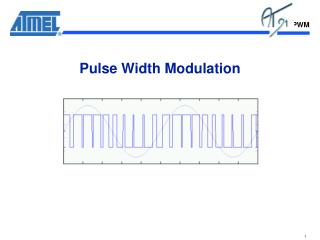
Pulse-Width Modulation (PWM)
Pulse-Width Modulation (PWM). Discussion 13.1 Example 35. Motor Driver Circuit. Solid-state relay. MOS FET Relays. G3VM-61B1. Motor – Generator Experiment. Using an AC Relay. Pulse-Width Modulation. Pulse-Width Modulation. pwm4.v. // Example 35a: PWM signal module pwm4(

Pulse-Width Modulation (PWM)
E N D
Presentation Transcript
Pulse-Width Modulation (PWM) Discussion 13.1 Example 35
Motor Driver Circuit Solid-state relay
MOS FET Relays G3VM-61B1
pwm4.v // Example 35a: PWM signal module pwm4( input wire clk, input wire clr, input wire [3:0] duty, input wire [3:0] period, output reg pwm ); reg [3:0] count; wire set, reset; // 4-bit counter always @(posedge clk or posedge clr) if(clr == 1) count <= 0; else if(count == period-1) count <= 0; else count <= count + 1;
pwm4.v (cont.) assign set = ~| count; assign reset = (count == duty); always @(posedge clk) begin if(set == 1) pwm <= 1; if(reset == 1) pwm <= 0; end endmodule
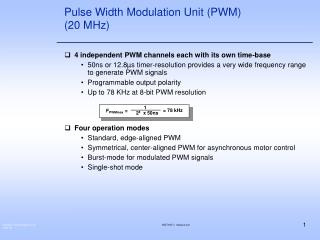
4 MHz clock on PLDT-3 board 17-bit counter will count from 0 to 131,072 in 32.768 ms. To get a 20 ms period, set period = (20/32.768)*131072 = 80000 (13880 hex) duty = 6000 1770 hex duty = 4400 1130 hex duty = 7600 1DB0 hex
// Example 35b: General PWM signal module pwmg #(parameter N = 17) (input wire clk, input wire clr, input wire [N-1:0] duty, input wire [N-1:0] period, output reg pwm ); reg [N-1:0] count; wire set, reset; // N-bit counter always @(posedge clk orposedge clr) if(clr == 1) count <= 0; else if(count == period-1) count <= 0; else count <= count + 1; pwmg.v
pwmg.v (cont.) assign set = ~| count; assign reset = (count == duty); always @(posedge clk) begin if(set == 1) pwm <= 1; if(reset == 1) pwm <= 0; end endmodule