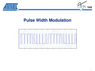
PWM Pulse Width Modulation
PWM Pulse Width Modulation. ME 4447/6405 November 6th, 2012. Ellen Qiulei Huang Juan Orphee Austin Farmer. Outline. Introduction -- What is PWM? Analog vs. Digital Actuation Consideration on PWM frequency Implementation on the HCS12 --Register Setup

PWM Pulse Width Modulation
E N D
Presentation Transcript
PWM Pulse Width Modulation ME 4447/6405 November 6th, 2012 Ellen Qiulei Huang Juan Orphee Austin Farmer
Outline • Introduction -- What is PWM? • Analog vs. Digital Actuation • Consideration on PWM frequency • Implementation on the HCS12 --Register Setup • Examples of PWM configuration using assembly and C -- Applications of PWM
Presenter: Ellen Qiulei Huang • Introduction -- What is PWM? • Analog vs. Digital Actuation • Consideration on PWM frequency • Implementation on the HCS12 -- Register Setup • Examples of PWM configuration using assembly and C -- Applications of PWM
Ellen Qiulei Huang What is PWM? • Pulse Width Modulation (PWM) is a technique for delivering partial power to a load via digital means. • The on-off behavior changes the average power of signal. • Output signal alternates between on and off within specified period. • http://www.youtube.com/watch?v=Lf7JJAAZxEU
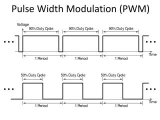
Ellen Qiulei Huang Duty Cycle A percentage measurement of how long the signal stays on. On Off VH Duty Cycle (D) VL Period (T)
Ellen Qiulei Huang Duty Cycle • Duty Cycle: • Average signal : (Usually, VL is taken as zero volts for simplicity.) On Off VH Duty Cycle (D) VL Period (T)
Ellen Qiulei Huang Duty Cycle Characteristic • The average value of a PWM signal increases linearly with the duty cycle
Ellen Qiulei Huang Types of PWM – Left Aligned • Lead edge is fixed, the trailing edge is modulated. On Off On Off Vhi Vhi Duty Cycle ~30% Duty Cycle ~60% Vlo Vlo Period Period
Ellen Qiulei Huang Types of PWM – Right Aligned • Trailing edge is fixed, lead edge is modulated. Off On On Off Vhi Vhi Duty Cycle ~30% Duty Cycle ~60% Vlo Vlo Period Period
Ellen Qiulei Huang Types of PWM – Center Aligned • Center of signal is fixed, both edges are modulated Off On Off Off On Off Vhi Vhi Duty Cycle ~30% Duty Cycle ~60% Vlo Vlo Period Period
Ellen Qiulei Huang Analog Generation of PWM • Analog PWM signals can be made by combining a saw- tooth waveform and a sinusoid • PWM output is formed by the intersection of the saw-tooth wave and sinusoid. • PWM toggles when sine equals saw-tooth.
Ellen Qiulei Huang Digital Generation - Delta Method • Limit signals are offset from a reference • When output signal reaches limits, PWM state changes
Ellen Qiulei Huang Digital Generation - Delta Method • Quantizer converts the difference between output and limits. • Quantizer can be realized with a comparator whose output is 1 or 0 if the input signal is positive or negative.
Ellen Qiulei Huang Digital Generation - Delta Sigma Method • PWM signal generated by Delta method • Error = Ref – PWM • Error is integrated. When integration signal reaches limit, PWM state changes.
Ellen Qiulei Huang Digital Generation - Delta Sigma Method
Ellen Qiulei Huang Choosing your PWM frequency Input signal (PWM) Ripple Output signal (actuator response)
Ellen Qiulei Huang Choosing your PWM frequency • Resolution: Inversely proportional to the number of distinct duty cycles you can generate for a given period • Transitions can only occur on a clock tick • Frequency limited by your clock and desired resolution • Example: 8 MHz clock, choose PWM to be 4 MHz • Limited resolution: only 3 duty cycles to choose from
Ellen Qiulei Huang Avoid ripple, Resolution loss, Power loss, Human hearing Consideration on PWM frequency Upper Limits Lower Limits Must be at least 10 times higher than the control system frequency Higher than 20kHz – audible frequency of sounds to avoid annoying sound disturbances. If too low the motor is pulsed, not continuous, because the motor’s inductance can not maintain the current Inverse of frequency should be much less than the motor/load time constant Higher error from ripple voltages If too high the inductance of the motor causes the current drawn to be unstable MOSFET transistor generates heat during switching Limited by resolution of controller Eddy currents generated in electromagnetic coils which lead to adverse heating Heat losses in electromagnetic materials is proportional to frequency squared
Ellen Qiulei Huang Advantages of PWM • Average value proportional to duty cycle, D • Low power used in transistors used to switch the signal • Fast switching possible due to MOSFETS and power transistors at speeds in excess of 100 kHz • Digital signal is resistant to noise • Less heat dissipated versus using resistors for intermediate voltage values
Cost Complexity of circuit Voltage spikes Susceptible to Electromagnetic Interference Ellen Qiulei Huang Disadvantages of PWM
Presenter: Juan Orphee • Introduction -- What is PWM? • Analog vs. Digital Actuation • Consideration on PWM frequency • Implementation on the HCS12 --Register Setup • Examples of PWM configuration using assembly and C -- Applications of PWM
Juan Orphee Pulse Width Modulator: PWM8B6CV1 • Use Port P • Six 8-bit channels or three 16-bit channels for greater resolution • Each channel produces an independent PWM signal • Two choices of clock sources per channel which provides for a wide range of frequencies
Juan Orphee PWM Block Diagram • -Each channel needs setup of the following registrars: • Enable/disable • Signal Polarity • Clock A or SA, B or SB • Prescale A and B clocks • Center Alignment Enable • Control Register • Prescale SA and SB clocks • Counter • Period • Duty Cycle • Emergency Shutdown Define PWM signal Vhi Duty Cycle Vlo Period
Juan Orphee PWM Register Memory Map
Juan Orphee 1-PWM Enable Register (PWME) • PWME in address: $00E0 • Set PWMEx to 1 to enable the channel • Set PWMEx to 0 to disable the channel
Juan Orphee 2-PWM Polarity Register (PWMPOL) • PWMPOL in address:$00E1 • Set PPOLx to 0, signal goes from low to high • Set PPOLx to 1, signal goes from high to low Signal Starts Here Zero Line
Juan Orphee 3-PWM Clock Select Register (PWMCLK) • PWMCLK in address: $00E2 • Set PCLK(5/4/1) 0 to use clock A • Set PCLK(5/4/1) 1 to use clock SA • Set PCLK(3/2) 0 to use clock B • Set PCLK(3/2) 1 to use clock SB Note: choice of Prescale will determine clock selection
Juan Orphee 4-PWM Prescale Clock Select Register (PWMPRCLK) • Located at $00E3 • Used to prescale clocks A and B Desired PWD Frequency N = bit resolution -Similar for Clock B Bus Clock HCS12 = 8 MHz -If calculated prescaler > 128 then use clock SA -How to convert time (e.g. in seconds) to cycles? Time (sec) x Clock Frequency = Time (sec) x (Buss Clock/Prescaler)
Computing a Prescaler Duty Cycle Time per clock cycle (sec) = Prescaler x Time (sec) per bus clock cycle 125x10(-9) sec for HCS12 -Resolution = Maximum Clock Counts -Example: An 8 bit counter can count 2^N-1 = 255 clock cycles T (sec) Period
Juan Orphee 5-PWM Center Align Enable Register(PWMCAE) • Located at $00E4 • Set CAEx to 0 for left align signal • Set CAEx to 1 for center align signal • Note: • Can only be set when channel is disabled
Left vs. Center Aligned Juan Orphee Not To Scale PWM Signal Starts
Juan Orphee 6-PWM Control Register (PWMCTL) • PWMCTL : Located at $00E5 • Set CONxy to 0 to keep 6 PWM channels separate (8-bit) • Set CONxy to 1 to concatenate PWM channels x and y together (16-bit). • x becomes the high byte and y becomes the low byte • Channel y determines the configuration • Bits PSWAI and PFRZ set either wait or freeze mode • Note • Changes only occur when both channels are disabled
Juan Orphee 7-PWM Scale A Register (SA Clock) (PWMSCLA) • Located at $00E8 • Programmable scaling of clock A to generate clock SA • Note
Juan Orphee PWM Scale B Register (PWMSCLB) • Located at $00E9 • Programmable scaling of clock B to generate clock SB • Note
Juan Orphee 8-PWM Channel Counter Register (PWMCNT) • Located at $00EC through $00F1 • One per channel • It tracks the cycle counts • When channel is enabled up-count starts • Note • Writing to counter while a channel is enable can cause irregular PWM cycles
Counter: Left vs. Center Aligned Juan Orphee • In the left aligned mode, the PWM counts up until (period-1) and resets to zero. • In the center aligned mode, the PWM counts up until (period-1) and counts down to zero. • Note: Period (PWMPER) is expressed in number of cycles PWM Signal Starts
Juan Orphee 9-PWM Channel Period Register (PWMPER) • Located at $00F2 through $00F7 • PWMPERx • Store a hexadecimal value to limit maximum value of counter • Note : Changes occur when one of following happen • Current period ends • Counter is written to • Channel is disabled =$00F2 • What is my PWMPER? • PWMPER (cycles) = PWM Period(sec) x Clock Freq(cycles/sec)
Juan Orphee 10-PWM Channel Duty Register (PWMDTY) • Located at $00F8 through $00FD • Store a hexadecimal value to control when signal changes • Changes occur when: • Current period ends • Counter written to • Channel is disabled • e.g for 60% duty cycle: PWMDTY = 0.6xPWMPER (in cycles)
Juan Orphee 11-PWM Shutdown Register (PWMSDN) $00FE
Presenter: Austin Farmer • Introduction -- What is PWM? • Analog vs. Digital Actuation • Consideration on PWM frequency • Implementation on the HCS12 - Register configuration • Example of PWM configuration using Assembly and C Code • Applications of PWM
Austin Farmer PWM Configuration Example • Use PWM Channel 0 • Positive polarity (signal goes from high to low) • Left aligned output • Frequency: 40 kHz • Period = 1/Frequency = 1/40 kHz = 25 μs • Choose clock source using resolution: • Bus clock frequency: 125 ns 25 μs / 125 ns = 200 cycles • 200 < 255, select clock A with prescaler = 1 • Duty Cycle = 50% • (50% * 200 cycles) = 100 cycles
Austin Farmer Configuration Example: Assembly Code PWME EQU $00E0 * 1-PWM Enable Register PWMPOL EQU $00E1 * 2-PWM Polarity Register PWMCLK EQU $00E2 * 3-PWM Clock Select Register PWMPRCLK EQU $00E3 * 4-PWM PrescaleClk Select Reg. PWMCAE EQU $00E4 * 5-PWM Center Align Enable Reg. PWMPER0 EQU $00F2 * 9-PWM Channel 0 Period Register PWMDTY0 EQU $00F8 * 10-PWM Channel 0 Duty Register ORG $1000 LDAA #$01 STAA PWMPOL *Positive polarity (starts high) LDAA #$00 STAA PWMCAE *Left aligned output STAA PWMCLK *Use Clock A STAA PWMPRCLK *Clock A prescaler = 1 LDAA #$C8 STAA PWMPER0 *Period =(25μs/125ns)= 200 = $C8 LDAA #$64 STAA PWMDTY0 *Duty cycle=(200*50%)= 100 = $64 LDAA #$01 STAA PWME *Enable PWM Channel 0 ...
Austin Farmer Configuration Example: C Code #include <hidef.h> /* common defines and macros */ #include <mc9s12c32.h> /* derivative information */ #pragma LINK_INFO DERIVATIVE “mc9s12c32” // Set up chip in expanded mode MISC = 0x03; PEAR = 0x0C; MODE = 0xE2; //Set up PWM Registrer PWMCLK = 0; // Sets source clock to clock A PWMPOL = 1; // Positive Polarity (signal goes from high to low) PWMCTL = 0; // Makes all channels 8-bit PWMCAE = 0; // Signals are left aligned PWMPER0 = 200; // Sets the period of the signal to 200 clock cycles PWMDTY0 = 100; // Makes the duty cycle 100 clock cycles (50% of 200) PWMPRCLK = 0; // Sets the prescaler to 1 PMWE = 1; // Enables and starts Channel 0 of PWM ….
Austin Farmer Motivation for PWM • In the past, motors were controlled at intermediate speeds by using variable resistors to lower delivered power (inefficient) • Example: Foot pedal on sewing machines is a variable resistor connected in series to control speed • PWM provides a more compact way of applying adjustable power to devices
Austin Farmer Applications of PWM • Voltage regulation • DC Motors • Telecommunications • Audio and Video Effects
Austin Farmer Application: Voltage Regulation • PWM is used in efficient voltage regulators • With appropriate duty cycle, the output will approximate voltage at the desired level • Switching noise can be filtered
Austin Farmer Application: DC Motors • Commonly used to control the speed of a DC motor • Continuous application of PWM cycle results in average voltage being applied to motor • Output speed of motor is proportional to input voltage • http://www.youtube.com/watch?v=Lf7JJAAZxEU • Used in Lab 3
Austin Farmer Application: Telecommunications • Pulses of various lengths will be sent at regular intervals (the carrier frequency of the modulation) • The widths of the pulses correspond to specific data values encoded at one end and decoded at the other • Leading edge of the data used as clock because small offset is included • More resistant to noise effects than binary data alone
Austin Farmer Applications: Audio and Video • In audio circuits, PWM can produce an effect similar to a chorus • Used in new class of efficient audio amplifiers • PWM dimming provides superior color quality in LED video display (millions of colors)