Download

1 / 32
350 likes | 550 Views
Electro-Optic Bunch Length Monitor. David Fritz LUSI. Motivation. Non-invasive absolute bunch length monitor - Transverse deflection cavities are invasive - Transition radiation monitors do not yield the absolute bunch length

E N D
Electro-Optic Bunch Length Monitor David Fritz LUSI
Motivation • Non-invasive absolute bunch length monitor • - Transverse deflection cavities are invasive • - Transition radiation monitors do not yield the absolute bunch length • Non-invasive time of arrival diagnostic (real time jitter measurement)
Electromagnetic Fields of the SPPS Electron Bunch • Approximate field assuming: • (close to bunch) • Steady-state • For bunch propagating with electromagnetic field indistinguishable from a pulse of plane polarized electromagnetic radiation 3.4nC
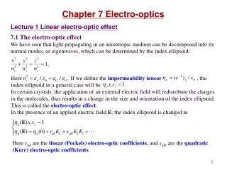
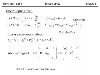
Electro-Optic Effect index ellipsoid
DC Linear Electro-Optic Effect (Pockels) +V EO crystal Polarizer p polarized s polarized -V
SPPS EO Chamber • EOS crystal on rotary actuator allows experimentation with different materials
EOS Bunch Length Measurement EO Crystal
Spatially Resolved Electro-Optic Sampling (EOS) Laser probe later relative to electron bunch Laser probe earlier relative to electron bunch EO Crystal
Spatially Resolved EOS Detection time polarizing beamsplitter integrated intensity time; space time integrated intensity Arrival time and duration of bunch is encoded on profile of laser beam
EOS measure of e- bunch compressionresolution limited by crystal
The jitter problem for multi-shot acquisition Master Clock Reference RF RF Distribution Network Accelerating Elements Experimental Pump Laser Electron Gun Sources of Short Term Jitter • RF distribution • e-beam phase to RF phase • End Station Laser phase to RF phase Limited to ~ 1 ps !
Indirect X-ray Pulse Arrival Time at SPPS D undulator amp EXP osc. A. Cavalieri et al., Phys. Rev. Lett. 94 144801, 2005
Temporal Resolution Limitations • Probe pulse duration
Effect of Long Pulse Probe Laser • Probe pulse longer than e-bunch • EO signal will be broadened • If probe pulse shape is very well known, we should be able to deconvolve e-bunch shape • Signal to background problems introduced • Probe pulse uncompressed (~10’s of picoseconds or longer) • Measurement will yield no spatially dependent signal
Temporal Resolution Limitations • Probe pulse duration • Imaging
EO crystal imaging CCD • 10 fs = 6 um extent across EO crystal at 30° incidence angle • Vacuum ports and other optics reduce angular resolution • Object does not lie in a plane perpendicular to optical axis • High resolution is required over a large depth of field (for adequate single-shot window)
Diffraction Effects in EOS Signal • EO crystal and effect combine to behave like a rectangular slit in the laser probe with single-lens imaging S-polarized P-polarized
Temporal Resolution Limitations • Probe pulse duration • Imaging • EO Crystal Properties
Frequency components of a 50 fs half-cycle pulse • Typical EO materials are ionic crystals and have a phonon resonance • somewhere in this frequency range. Ω F+ F- - + E (ω=Ω)
Optical Dispersion Relation Attenuation
THz Pulse in the EO Sensor FFT R, Absorption IFFT
ZnTe Phase-Matching Characteristics • 1st phonon resonance at ~ 5.3THz • EO frequency response to ~ 4THz
GaP Phase-Matching Characterisitcs • 1st phonon resonance at ~ 11THz • EO frequency response to ~ 8THz
A new EO material? EO coefficient 3x greater than ZnTe and 12x GaP But what is the frequency response?
Acknowledgements D.A. Reis1,2, B. Adams3, R. Akre4, J. Arthur5, C. Blome6, P.H. Bucksbaum4,7, A.L. Cavalieri8, S. Engemann5, S. Fahy9, R. W. Falcone10, P. H. Fuoss11, K. J. Gaffney5, M.J. George5, J. Hajdu12, P. B. Hillyard13, M. Horn-von Hoegen14, M. Kammler15, J. Kaspar13, P. Krejcik4, S. H. Lee1, A.M. Lindenberg5, B.McFarland7, D.Meyer13, T.Montagne4, E. D.Murray9, Nelson16, M. Nicoul14, R. Pahl17, J. Rudati3, H. Schlarb6, D. P. Siddons18, K. Sokolowski-Tinten14, Th. Tschentscher6, D. von der Linde14 & J. B. Hastings5 1 FOCUS Center, Departments of Physics and Applied Physics Program, University of Michigan 2 PULSE Center, Stanford Linear Accelerator Center 3 Advanced Photon Source, Argonne National Laboratory 4 Stanford Linear Accelerator Center 5 Stanford Synchrotron Radiation Laboratory/SLAC 6 Deutsches Elektronen-Synchrotron DESY, Hamburg, Germany 7 Departments of Physics and Applied Physics, Stanford University 8 Max-Planck-Institute of Quantum Optics, Garching, Germany 9 Department of Physics and Tyndall National Institute, University College, Cork, Ireland 10 Department of Physics, University of California, Berkeley 11 Materials Science Division, Argonne National Laboratory 12 Department of Cell and Molecular Biology, Biomedical Centre, Uppsala University, Sweden 13 Department of Chemistry, Stanford University 14 Institut fur Experimentelle Physik, Universitat Duisburg-Essen, Germany 15 Institut fur Halbleitertechnologie, Universitat Hannover 16 Lawrence Livermore National Laboratory 17 Consortium for Advanced Radiation Sources, The University of Chicago 18 National Synchrotron Light Source, Brookhaven National Laboratory This work was supported in part by the: US DoE, BES NSF FOCUS physics frontier center Stanford PULSE center Swedish Research Council Irish Research Council Science Foundation Ireland Keck Foundation Deutsche Forschungsgemeinschaft