Download
1 / 19
190 likes | 332 Views
BI Day ---- Convention Centre of Archamps 6 th of Dec. 2012. Electro-Optic Bunch Profile Monitor for the CERN-CTF3 probe beam. R. Pan, T. Lefevre , S.P. Jamison, W.A. Gillespie CERN STFC Daresbury Laboratory University of Dundee. Outline. Introduction for CALIFES.

E N D
BI Day----Convention Centre of Archamps 6th of Dec. 2012 Electro-Optic Bunch Profile Monitor for the CERN-CTF3 probe beam R. Pan, T. Lefevre , S.P. Jamison, W.A. Gillespie CERN STFC Daresbury Laboratory University of Dundee
Outline Introduction for CALIFES EOSD principle and Simulation EO bunch profile monitor system Resolution Summary
Introduction ---- CALIFES 3 single klystron Standing-wave photo-injector 4 4 to Two Beam Test Stand (TBTS) RF network 1 6 5 2 Complete set of diagnostics 3 travelling-wave structures (LIL) Existing bunch profile monitor: Deflecting cavity (bunch head downward, tail upward) Bunch length measurement with an acceleration structure (bunch head decelerated, tail accelerated)
Coulomb field of e-bunch Coulomb field temporal profile β=0 β=0.9 β=0.9999 Coulomb field of one electron • High energy , Coulomb field temporal profile is approximately the bunch temporal profile • Broadening of profile:
Simulation: Coulomb field of e-bunch • Radial offset from single electron • Electrons’ density distribution within one bunch • Convolution Coulomb field temporal profile and broadening 2% r0: the distance far away from e-bunch For high energy beam (200 MeV): Broadening rate < 2% @ 10 mm Closer Further Damage to crystal Crystal survives, low Coulomb field
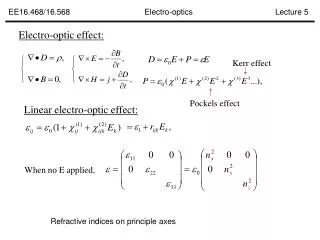
Simulation: EOSD EO bunch profile measurements: --EO spectral decoding --EO temporal decoding --EO spatial encoding --EO up conversion Electro-Optical Spectral Decoding: • Linear chirped optical pulse • Polarization variation caused by Coulomb field—laser nonlinear effect • Polarization Intensity, by two crossed polarizers • I(λ) I(t) ----rotation matrix ----Jones matrix for quarter waveplate ----Jones matrix for half waveplate
Simulation: EO phase mismatching induce EO effect: Frequency mixing Polarization variation Coulomb field Laser Wider bandwidth, better resolution !
Simulation: EOSD results and limitation distortion Other parameters: Laser wavelength: 780nm Laser pulse energy: 1.5nJ Pulse duration: 150fs Short bunch----fast temporal modulation---- spectral content ---- t~λ mapping Crystal thickness: 1mm Distance: 5mm
EO monitor Design for CALIFES • Stretcher: • SF11 glass • 100fs----3.24ps Actuator Cameras Rotation stage
Laser system Laser system 37.5 MHz 75 MHz Laser head and controller Custom Erbium fiber laser with pulse picker PD in RF 1 RF 2 PID: Proportional Integral Differential Phase out PID in Motor control Piezo control Synchronization box
Timing and synchronization scheme RF (74.963 MHz, 13.3ns) Phase shifter Streak Camera Pulse generator OTR e- 5 Hz rep. RF (37.4815 MHz, 26.6 ns) Ref (74.963 MHz) RF (74.963 MHz) Optical system Photodiode (5 ns) Amplifier Oscillator Pulse picker signal (fibre, 20m, ~100 ns) Delay stage (6 fs step, 0.75 ns range) ICCD Camera Trigger from the accelerator 3 ns min. exposure
EO monitor Design for CALIFES Chamber design OTR <001> First chamber includes a mirror The second chamber includes a mirror, a crystal and a OTR screen <-110> Crystal orientation <010> <100> <-1-10>
Laser/OTR Transfer Line Streak camera room CLEX CLEX Laser lab We transfer the 780nm fs laser from our laser lab (building 2010-1-002) to CLEX, and transfer the OTR photons from CLEX to our lab.
Laser/OTR Transfer Line 2 Installation: Take the box1 and box2 for example Mirror/lens cover box
Expected Resolution 1. Distance between crystal and e-beam ~10 fs at r=5 mm 2. The frequency response of crystal (material and thickness) for 1 mm ZnTe: ~333 fs ~1/(3THz) 3. EOSD limitation (Laser pulse duration and chirped duration) ~550 fs (100 fs3 ps) 4. Resolution of spectrometer and CCD ~40 fs (512 pixels) Grating
Summary & Outlook Summary: EO technique is a non-destructive testing technique, and has the feasibility in fs resolution. System simulation, designs of laser system, transfer line, chambers, detection system and timing and synchronization have done. Based on numerical simulation, the resolution of this system is expected to be sub-picosecond. Outlook: The system waiting for being installed during the winter shut down. First measurement in the beginning of next year. Resolution improvement study This research project has been supported by a Marie Curie Early Initial Training Network Fellowship of the European Community’s Seventh Framework Programme under contract number (PITN-GA-2008-215080-DITANET)
References [1] X. Yan, A. M. MacLeod, W. A. Gillespie, G. M. H. Knippels, D. Oepts, A. F. G. van der Meer and W. Seidel, Phys. Rev. Lett. 85, 3404 (2000). [2] I. Wilke, A. M. MacLeod, W. A. Gillespie, G. Berden, G. M. H. Knippels, and A. F. G. van der Meer, Phys. Rev. Lett. 88, 124801 (2002). [3] A. Azima, S. D¨usterer, H. Schlarb, J. Feldhaus, A. Cavalieri, D. Fritz, and K. Sengstock, In Proceedings of the EPAC 2006, Edinburgh, Scotland, 2006, p. 71. [4] G. Berden, S. P. Jamison, A. M. McLeod, W. A. Gillespie, B. Redlich, and A. F. G. van der Meer, Phys. Rev. Lett. 93, 114802 (2004). [5] S. P. Jamison, G. Berden, P. J. Phillips, W. A. Gillespie, and A. M. MacLeod, Appl. Phys. Lett. 96, 231114 (2010). [6] J. D. Jackson. Classical Electrodynamics (John Wiley and Sons, Inc., 1999). [7] S. P. Jamison, A. M. MacLeod, G. Berden, D. A. Jaroszynski, W. A. Gillespie, Opt. Lett. 31, 1753 (2006). [8] S.P. Jamison, G. Berden, W.A. Gillespie, P.J. Phillips, A.M. MacLeod, in Proceedings of EPAC08, Genoa, Italy, 2008, p. 1149. [9] J. Breunlin, Diploma thesis, University Hamburg, 2011. [10] B.Steffen et al., Phys. Rev. ST Accel. Beams 12, 032802 (2009). [11] A. Yariv. Quantum electronics (1989).