Download
1 / 20
200 likes | 386 Views
WP: CTC-006 - beam instrumentation task3 CLIC Electro-Optic Bunch Temporal Profile Monitor. Allan Gillespie 1 , David Walsh 1,2 , Steve Jamison 2 , Rui Pan 1, 3 , Thibaut Lefevre 3. 1 C arnegie Laboratory of Physics, University of Dundee, Dundee DD1 4HN, UK

E N D
WP: CTC-006 - beam instrumentation task3 CLIC Electro-Optic Bunch Temporal Profile Monitor Allan Gillespie1 , David Walsh1,2, Steve Jamison2, RuiPan1, 3, ThibautLefevre3 1Carnegie Laboratory of Physics, University of Dundee, Dundee DD1 4HN, UK 2 Accelerator Science &Technology Centre (ASTeC), STFC Daresbury Laboratory, Warrington WA4 4AD, UK 3Beam Department, CERN, CH-1211 Geneva 23, Switzerland Synopsis: Activities at CLIC CALIFES Activities at STFC Daresbury Laboratory Activities at the University of Dundee Planned group activities over next year
1. CALIFESElectro-Optic Bunch Profile Monitor Development & commissioning of single-shot EO bunch profile monitor ̶ low time resolution system (~1ps) Progress update (Rui Pan) Planned EO monitor simulated and resolution calculated Overall EO system for CTF3 designed Laser system designed and purchased Laser system and ancillary optics arrived Control system design completed All cables and optical fibres installed Optical synchronization system designed Transfer lines for laser and OTR photons designed Laser laboratory under preparation Camera and motors are being delivered Two monitor vacuum chambers are being designed Preliminary work completed for beam profile measurement
EO monitor Standing-wave photo-injector 4 to Two Beam Test Stand (TBTS) RF network Complete set of diagnostics 3 travelling-wave structures (LIL) • Existing bunch profile monitors: • RF deflecting cavity • Bunch length measurement with 12 GHz high gradient acceleration structure (2 beam test stand)
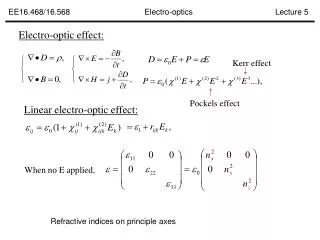
Electro-Optical Spectral Decoding Simulations of bunch-induced polarisation change and non-linear interaction Spectral Decoding (EOSD): The Coulomb field temporal profile of the e-bunch is encoded on to a time-wavelength correlated optical probe pulse. The profile is read-out through the spectrum of the probe pulse. Where, Where,
Simulation: Coulomb field of e-bunch and broadening • At high energies , the Coulomb field temporal profile is approximately the bunch temporal profile • Broadening of profile from transverse parameters: β=0 β=0.9 β=0.9999 4% For high energy beam (>150 MeV), resolution broadening is < 4% @ 10 mm r0 = transverse separation from e-bunch As r0 increases, Coulomb field decreases
Simulation: limitations of EOSD Interleaving bandwidth conflict for optical probe and bunch spectra Without distortion distortion Other parameters: Laser wavelength: 780nm Laser pulse energy: 1.5nJ Pulse duration: 150fs Result is distortion for bunch lengths < 1 ps Crystal thickness: 500μm Crystal separation: 5mm Reason: Short bunch induces fast temporal modulation, which modifies spectral content and thus distorts t λmapping
Implementation of the EO monitor at CALIFES Diagnostic section Accelerating structure Photo-injector Beam direction Grating P: Polarizer H: Half wave plate Q: Quarter wave plate : Mirror with actuators : Finger camera Laser: Wavelength: 780 nm Duration: 100 fs Repetition: 37.4815 MHz Pulse energy: 2.7 nJ Crystal: Thickness: 1mm Separation: 5-10 mm In Lab In CLEX 1 Laser 1 ICCD Camera 1 Motor stage 10 Plane mirrors 3 Gratings 3 Lenses 1 Fibre head 7 Plane mirrors 2 Polarizers 2 Wave plates 1 Lens 1 Fibre head 10 Actuators 3 Rotation motors Finger cameras
Laser ↔ e-bunch synchronization Non-standard design, providing higher pulse energy Laser Laser parameters Wavelength: 780 nm & 1560 nm Duration: <120 fs Repetition: 74.9 MHz @ 1560 nm 37.5 MHz @ 780 nm Pulse energy: 4.4 nJ @ 1560 nm 2.7 nJ @ 780 nm • Synchronization between laser pulse and e-bunch • Laser synchronised to accelerator RF (75MHz) at <200fs level. • OTR light transported to laser lab, providing beam arrival time monitor • Laser transported from same screen • Streak camera monitors few ps beam-laser synchronisation. • Optical delay for sub-ps to ns timing adjustments 37.5 MHz 74.9 MHz (2) Spectral characterisation of the post-interaction laser pulse A low jitter (<1ns) signal triggers the iCCDcamera, gating a single laser pulse => can choose which electron bunch to characterise
Optical Transfer Line Relay lenses stabilise optical transport (1) Laser transfer line: from the laser lab to CLEX ZEMAX simulation (purple dots are the centre wavelength) Transfer the laser to the machine. The measured signal will be transferred back to the lab by optical fibre. (2) OTR photons transfer line: from CLEX to the camera lab Transfer OTR photons and laser photons to a streak camera for synchronization
Contributions to System Time Resolution 1. Distance between crystal and e-beam ~10 fs at r=5 mm 2. The frequency response of crystal (material and thickness) for 1 mm ZnTe: ~333 fs ~1/(3THz) 3. EOSD limitation (Laser pulse duration and chirped duration) ~550 fs( for 100 fs pulse chirped to 3ps) 4. Resolution of spectrometer and iCCD ~3 fs ICCD Grating Mirror
2. Activities at STFC Daresbury Laboratory Testing optical requirements for ultimate time resolution monitor Spectral Upconversion Techniques Convert the far-IR – mid-IR spectrum to an optical spectrum • Offers potential for simple & robust bunch form factor measurements • - Bandwidth reduction 1mm - 10m 800nm – 740nm • - Simple CW lasers (?) 2011/12 experiments at Daresbury (Manchester University also collaborating) Shooting for ultimate aimof CW laser probe: • - Simple 200mW diode laser, ALICE macrobunch CSR • wavelength drift believed to be obscuring the very small signal • 2 Watt single mode (MHz linewidth) laser installed (loan through University of Manchester collaboration) Continuing absence of signal attributed to long bunch, low CSR energy, & radiation transport losses. Change of approach....Use laser-generated THz for initial parameter setting experiments
Laser-generated THz pulses as mimic of electron bunch MV/m sub-ps source available with independent EO characterisation (separate project in high power THz generation for bunch manipulation) Still failed to observe signal using single-mode laser - believe currently just below signal-noise of detection systems EO crystal efficiency, ITO dichroic losses, shorter pulse/larger bandwidth => smaller I (l) per nm ...returning to understanding of signal-noise levels with “quasi-CW” laser - kW equivalent laser power trivially available (~50ps 1064nm system to be used initially). - small increase in complexity through synchronisation Sub-picosecond pulse generation and detection in ASTeC laser lab Upconversion of CTR on ALICE Experiments for May 2012 delayed due to unscheduled cathode replacement (underway now)
3. Activities at the University of Dundee Development of alterative higher bandwidth non-linear materials EO Detection solution in thin films & 2D structures - to bypass propagation effects Thin film polymers • Demonstrated broadband EO response • Sufficient EO efficiency • ?? Accelerator environment, material stability ?? Nano-structured materials • Electro-optic effect from short-range structure. • ... limited experimental demonstrations Materials, Photonics & Smart Systems (MAPS) Group at Dundee Fabrication & Applications of Nanocomposites Dundee group expertise: DC electric field-assisted selective dissolution of nanoparticles in nanocomposites (patented technology)
Overall R&D goals Progress • Fabricate percolation films and metal-dielectric nanocomposite films at Dundee University → a type of “metamaterial” - utilising electric field & laser processing of materials • Test these films for the required E-O properties at Daresbury Laboratory • Incorporate materials into set-ups at PSI and CLIC 3 nanosecond laser systems (at wavelengths 355, 532 and 1064 nm) in place during 2011 for materials processing (£180,000 investment) Picosecond (Coherent Talisker ULTRA 355-04) system being installed (May 2012) Operates at same 3 wavelengths (£240,000 investment) Taliskerpulsewidth <15ps with an average power of up to 4W at 355nm, 8W at 532nm, and 16W at 1064nm. First tests on new system planned for early June 2012
Summary • CALIFES preparations progressing well • Vacuum chambers to be installed during next shutdown (June 2012) • Laser laboratory under preparation, laser systems being installed May 2012 • Daresbury experiments on spectral upconversion beginning to show results • Separate ASTeC project underway in high power THz generation for bunch manipulation • Dundee laser systems for processing alterative higher bandwidth non-linear materials are now in place, and will soon be available for regular use • Preparation and testing of silver & gold metal-dielectric nanocomposites (MDNs) are planned for near future
Planned activities for year 2 of project • Optical synchronization system implemented at CALIFES, and transfer lines installed for laser and OTR photons. • Laser and control systems completed and tested • First beam tests at CALIFES • “Conventional” E-O materials (organic crystals, thin film polymers, etc) tested and characterised at Daresbury • First MDN metamaterials produced at Dundee and evaluated at Daresbury • Arrangements put in place to test first high-resolution prototype system at PSI test facility
Plans for Longitudinal PM during the PPP • R&D on Electro-optical techniques on single shot temporal decoding techniques • Shortest measured electron bunch profile (at DESY FLASH) using 65um thick GaP crystal The optimum fitted Gaussian curve sigma is 79.3 7.5 fs By S. Jamison and A. Gillespie Status of the CLIC instrumentation
Plans for Longitudinal PM during the PPP • Improving the encoding process • Investigation of new electro-optic • materials for EO profile systems at CLIC • Experimental characterisation of thin films • and meta-materials as novel EO detectors. • Demonstration of the concept of a multiple • crystal detector spanning a wide optical bandwidth • Improving the decoding process • Demonstration of single-shot X-FROG measurements on a laser-generated THz source. • Demonstration of X-FROG detection on an electron beam source. By S. Jamison and A. Gillespie Status of the CLIC instrumentation