Download
1 / 21
220 likes | 256 Views
Learn about software components, their interfaces, and deployment diagrams in UML. Explore notations, examples, and key elements to effectively model your system.

E N D
Unified Modelling Language Component and Deployment Diagrams
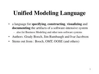
What is a component? • A software component is a modular part of a system • It is the software implementation of one or more classes • Provides interfaces to other components • In UML 1.x, a component represented implementation items, such as files and executables • In UML 2.0 components are considered encapsulated units within a system or subsystem that provide one or more interfaces • The physical items that UML1.x called components are now called "artifacts" in UML 2 - an artifact is a physical unit, such as a file, executable, script • Components can be flexibly REUSED and REPLACED
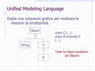
Component Diagram • A component diagram shows the various high-level components in a system, and their dependencies
Component Diagram Notation in UML 1.x • This is also supported in UML 2.0
Component Diagram Notation in UML 2.0 – different possible notations
Modeling a component's interfaces (1) • A provided interface • Characterize services that the component offers to its environment • A required interface • Characterize services that the component expects from its environment • Two notations for representing the interfaces
Example (UML1.x)Component diagram for the "Courseware Management System "
Deployment Diagram • The deployment diagram shows how a system will be physically deployed in the hardware environment • Its purpose is to show where the different components of the system will physically run and how they will communicate with each other • This diagram is more useful when a system is built and ready to be deployed
Deployment Diagram vs Component Diagram • While components provide the application functionality, the deployment diagram elements provide the necessary environment for the components to execute in • Components can also be shown on a Deployment diagram to show the location of their deployment
Artifact • An artifact is a classifier that represents some physical entity, a piece of information that is used or is produced by a software development process, or by deployment and operation of a system
Point to Remember There is no substitute to experience in order to master UML diagrams. As you build more and more complex systems, you will evolve your skills and gain a deeper understanding and varied ways to utilize the power of UML diagrams
References • http://www.uml-diagrams.org/deployment-diagrams-examples.html • www.developer.com • The following link contains an example of an online shopping application and provides use case, sequence, communication, component and deployment diagrams • http://www.uml-diagrams.org/examples/online-shopping-example.html