
Memory Interfacing Techniques in Semiconductor Systems
E N D
Presentation Transcript
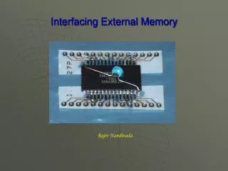
The memory is made up of semiconductor material used to store the programs and data. Three types of memory is • Process memory • Primary or main memory • Secondary memory
TYPICAL EPROM AND STATIC RAM: • A typical semiconductor memory IC will have N address pins, M data pins (or output pins). • Having two power supply pins (one for connecting required supply voltage (V and the other for connecting ground). • The control signals needed for static RAM are chip select (chip enable), read control (output enable) and write control (write enable). • The control signals needed for read operation in EPROM are chip select (chip enable) and read control (output enable).
DECODER: It is used to select the memory chip of processor during the execution of a program. No of IC's used for decoder is 2-4 decoder (74LS139) 3-8 decoder (74LS138) Fig - Block diagram and Truth table of 2-4 decoder
EXAMPLE-1 Consider a system in which the full memory space 64kb is utilized for EPROM memory. Interface the EPROM with 8085 processor. The memory capacity is 64 Kbytes. i.e 2^n = 64 x 1000 bytes where n = address lines. So, n = 16. In this system the entire 16 address lines of the processor are connected to address input pins of memory IC in order to address the internal locations of memory. The chip select (CS) pin of EPROM is permanently tied to logic low (i.e., tied to ground). Since the processor is connected to EPROM, the active low RD pin is connected to active low output enable pin of EPROM. The range of address for EPROM is 0000H to FFFFH.
EXAMPLE-2 Consider a system in which the available 64kb memory space is equally divided between EPROM and RAM. Interface the EPROM and RAM with 8085 processor. Implement 32kb memory capacity of EPROM using single IC 27256. 32kb RAM capacity is implemented using single IC 62256. The 32kb memory requires 15 address lines and so the address lines A0 - A14 of the processor are connected to 15 address pins of both EPROM and RAM. The unused address line A15 is used as to chip select. If A15 is 1, it select RAM and If A15 is 0, it select EPROM. Inverter is used for selecting the memory. The memory used is both Ram and EPROM, so the low RD and WR pins of processor are connected to low WE and OE pins of memory respectively. The address range of EPROM will be 0000H to 7FFFH and that of RAM will be 7FFFH to FFFFH.
EXAMPLE-3 Consider a system in which 32kb memory space is implemented using four numbers of 8kb memory. Interface the EPROM and RAM with 8085 processor.
Consider a system in which the 64kb memory space is implemented using eight numbers of 8kb memory. Interface the EPROM and RAM with 8085 processor. The total memory capacity is 64Kb. So, let 4 numbers of 8Kb EPROM and 4 numbers of 8Kb RAM. Each 8kb memory requires 13 address lines. So the address line A0 - A12 of the processor are connected to 13address pins of all the memory lCs. The address lines A13, A14 and A]5 are decoded using a 3-to-8 coder to generate eight chip select signals. These eight chip select signals can be used to select one of the eight memories at any one time.