Download
1 / 44
440 likes | 619 Views
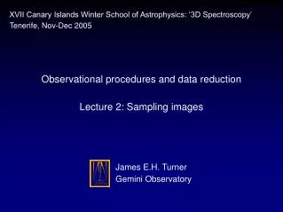
Observational procedures and data reduction Lecture 2: Sampling images. XVII Canary Islands Winter School of Astrophysics: ‘3D Spectroscopy’ Tenerife, Nov-Dec 2005. James E.H. Turner Gemini Observatory. Background: image sampling and IFUs.

E N D
Observational procedures and data reduction Lecture 2: Sampling images XVII Canary Islands Winter School of Astrophysics: ‘3D Spectroscopy’ Tenerife, Nov-Dec 2005 James E.H. TurnerGemini Observatory
Background: image sampling and IFUs • Sampling theory helps us understand the effects of dividing an image or waveform into discrete points (eg. CCD pixels) • Why is sampling theory relevant to IFUs? • It’s important for digital imaging in general (but not very well known outside the engineering community) • IFUs usually don’t have a simple square (or cubic) pixel grid; sometimes they don’t have a regular grid at all • Resampling (in up to 3D) is necessary if we want to get to a square/cubic grid that is straightforward to work with • IFS can involve 2 sampling stages—at the focal plane and at the detector • IFUs often undersample telescope images, for sensitivity reasons or to maxmize the field of view; need to understand the consequences
The ‘Sampling Theorem’ • Often named after one of several researchers: • Shannon, Nyquist & Hartley of Bell Labs, USA • Whittaker of Edinburgh University • Kotel’nikov of the Russian Academy of Sciences • eg. ‘Shannon-Whittaker-Kotel’nikov Theorem’ or ‘Nyquist Criterion’ • Deals with sampling on a regular grid • Roughly speaking, the basic idea is that an analogue signal containing a finite amount of information can be recovered completely from a large enough set of discrete samples • Leads to the commonly-cited ‘2 pixels per FWHM’ criterion in astronomy (more later)
The ‘Sampling Theorem’ (derivation) • For simplicity, consider the case of a one-dimensional function, f(x) • Use the Dirac delta function to represent sampling at a point, x’: • The delta can be any function with unit integral that is ‘infinitely narrow’, ie. zero everywhere except at x=0 • Thus multiplying a function by delta gives an impulse normalized to the value at the relevant point:(ie. the integral becomes f(x’) rather than 1) (2.1) x 0 f(x) (2.2) x’
The ‘Sampling Theorem’ (derivation) • A comb (/shah) function is an infinite series of equally-spaced deltas: • (the multiplicative |a| preserves the unit area of d when scaling the argument by the same factor) • So sampling f(x) at regular intervals of a is equivalent to multiplication by a comb function: • III.f is a series of impulses whose areas correspond to the sample values—it contains the same information from f(x) as would point-like measurements (2.3) -2a -a 0 a 2a (2.4)
The ‘Sampling Theorem’ (derivation) • The comb function is a useful way to represent sampling because its Fourier transform is also a comb function: • (defining frequency as 1/x, rather than 2p/x) • Convolution Theorem • Multiplying functions together in the spatial domain is equivalent to convolving their Fourier transforms (and vice versa) • So the Fourier transform of sampled data looks like this: (2.5) (2.6)
The ‘Sampling Theorem’ (derivation) • Graphically, the frequency spectrum of sampled data is the FT of the original continuous function f(x), replicated at intervals of 1/a: • (convolving F(u) with each d(u-u’) just shifts the origin to u’) • A function is said to be band-limited if its Fourier transform is zero above some cut-off frequency, uc • In the above figure, the replicas of F(u) don’t overlap if uc < 1/2a
The ‘Sampling Theorem’ (derivation) • If the replicas don’t overlap, we can separate out the original frequency spectrum, F(u), from the transform of the sampling pattern • The original f(x) can be recovered without any loss of information • If the replicas do overlap, the spectrum is not determined uniquely • The Sampling Theorem can therefore be stated as follows…
The ‘Sampling Theorem’ (derivation) • If the replicas don’t overlap, we can separate out the original frequency spectrum, F(u), from the transform of the sampling pattern • The original f(x) can be recovered without any loss of information • If the replicas do overlap, the spectrum is not determined uniquely • The Sampling Theorem can therefore be stated as follows… • ‘A band-limited function can be recovered completely from a set of regular samples, as long as the sampling rate is at least twice the highest component frequency of the waveform’ • 1/a > 2umaxa < lmin / 2
The ‘Sampling Theorem’ (derivation) • For a given sampling interval, the maximum recordable frequency of 1/2a is known as the Nyquist frequency • Likewise, the critical sampling rate for a waveform of a particular bandwidth is often called the Nyquist rate • (Sometimes these terms are interchanged or used for uc) • To recover the function before sampling, F(u) can be isolated by a box function with unit value between ±1/2a and zero value elsewhere: P
The ‘Sampling Theorem’ (derivation) • The box function, P(u/2uc), has Fourier transform 2uc sinc(2ucx) • Define sinc(x) = sin(px)/px (an infinite function with zeros at integer x): • So by the Convolution Theorem, f(x) is reconstructed in the spatial domain by a summation of (regularly spaced) sinc functions: 1 -2 2 -4 4 0 (2.7) (2.8)
The ‘Sampling Theorem’ (derivation) • Equation 2.8 specifies f(x) at all intermediate points between the sample positions • This is possible because f(x) contains a finite number of frequencies • The sincs are just another kind of basis functions, like Fourier series • The coefficients are just the sample values • Once we have reconstructed (interpolated) the original analogue telescope image, we can then resample it onto a convenient grid Sampled data convolved with sinc(x/a)
Undersampling • If f(x) contains frequencies greater than the Nyquist frequency 1/2a, then it is said to be undersampled • F(u) overlaps its satellite copies in the spectrum of the sampled data • Frequencies greater than 1/2a are aliased to lower frequencies • they are effectively wrapped around (reflected) at 1/2a
Undersampling • Physically, aliasing is due to beating between a frequency component and the sampling period • On a regular grid, high and low frequencies can appear the same at every sample point, even though their values are quite different in between: • The only way to distinguish between the aliases is to disallow the higher frequency in the first place: hence the band-limitation criterion
Undersampling • The power transfer from high to low frequencies creates artefacts in the reconstruction of f(x) • Super-Nyquist frequencies are not only unmeasurable but also contaminate otherwise good data • We end up with less useful information than if f(x) had been smoothed to a lower resolution (ie. band-limited) before sampling! • For irregular grids, the degeneracy between frequencies is broken • There is no aliasing as such, but information is still lost if the sampling rate is too low, which can lead to other reconstruction errors
Stop! That’s enough sampling theory • Well, almost… • For more information, see Bracewell: ‘The Fourier Transform and its Applications’ (2000 and earlier editions) • So now we know about sampling infinite band-limited functions • but what about real images?!
Sampling images: band limitation • When a plane wave passes through an aperture, it is diffracted so that a ray from any given direction spreads out in angle: • The far-field (Fraunhofer) diffraction pattern of the aperture—ie. amplitude as a function of angle—is described by its Fourier transform
Sampling images: band limitation • What we actually measure is intensity ( amplitude2), so we’re interested in the square of the Fourier transform • For a rectangular aperture, this is a product of sinc functions (as we saw earlier when taking the FT of a box function) • For a circular telescope mirror, it is the closely-related Airy pattern: • See Goodman (1968) or Hecht (1987) optics textbooks ‘First-order Bessel functionof the first kind’ Telescope diameter (2.9) Angle in radians Wavelength
Sampling images: band limitation Circular aperture diffraction intensity
Sampling images: band limitation • The finite image produced by an optical system in response to a point source is known as the point spread function (PSF) • For a diffraction-limited telescope, the PSF is just the Airy pattern • For a seeing-limited telescope, the PSF tends towards a Gaussian/Moffat profile given a long enough exposure (~60s) • Central Limit Theorem: repeated convolution tends to a Gaussian • The image formed by the telescope is an ‘infinitely’-detailed projection of the sky, convolved with the PSF • The power spectrum (Fourier transform amplitude) of the PSF is known as the modulation transfer function (MTF) • From the Convolution Theorem, this describes the sensitivity of the system to different spatial frequencies
Sampling images: band limitation • Since the diffraction PSF of a telescope is the squared Fourier transform of its aperture, the MTF is just the self-convolution of the aperture shape: • Therefore for a finite aperture, telescope images must be band limited Aperture transparency MTF r 1/q
Sampling images: diffraction-limited case • Sampling requirement • For a circular mirror of diameter D, the cut-off frequency turns out to be D/l cycles per radian (see Goodman, 1968) • To satisfy the Sampling Theorem, the pixel spacing must therefore be less than l/2D radians • The FWHM of an Airy pattern is 1.02l/D radians • So in terms of the PSF, the critical pixel spacing is 0.49 FWHM • So we arrive at the sampling criterion that astronomers are fond of… • For proper sampling of telescope images, the pixel size must be no greater than half the FWHM of a point source (really 0.49) • Strictly speaking, this applies only to diffraction-limited imaging
Sampling images: seeing-limited case • Seeing-limited images • Approximate the natural seeing by a Gaussian profile • FWHM typically an order of magnitude greater than the diffraction limit • This has a FT which is also Gaussian, ie. infinitely extended • Seeing-limited images don’t strictly have a high-frequency cut-off below the diffraction-limit, so theoretically we need FWHM ≥ ~20 the pixel size! • In practice it’s not quite that bad… • The Gaussian distribution and its transform can be written • For unit a, these have a standard deviation of 0.399 and a FWHM of 0.939 • The values actually die off quite fast after a few s (2.10)
Sampling images: seeing-limited case • If a Gaussian PSF is imaged with a FWHM of n pixels, then rewriting its Fourier transform in terms of FWHM (using na=0.939) we have • with u in cycles/pixel and s = 0.375/n • For n=2 pix FWHM, the Nyquist frequency of 0.5 cycles/pixel is at 2.7s • This far out, the Gaussian MTF value is only 2.8% of its peak • Super-Nyquist frequencies are heavily suppressed in amplitude to <3% • The total integrated power aliased back into the main spectrum is 0.7% • So even for seeing-limited images, the ‘2 pixel per FWHM’ criterion is good enough in most cases • A slightly higher number of pixels will reduce aliasing to very low levels (2.10)
Real-world issues: finite detector • The comb function used to model sampling is infinite, whereas detectors have ~103 pixels/axis and IFUs have only ~101 • A finite detector image is equivalent to a comb function multiplied by the telescope image, truncated with a box function of width npix a • The FT is therefore an infinite comb convolved with F(u), convolved with a narrow sinc function whose first zeros are at 1 / (npix a) • This is twice the Nyquist frequency divided by npix(ie. 2 pixels of the discrete Fourier transform…) • The convolution reflects the fact that a finite band-limited image is described by a finite number of frequency components; otherwise the FT of the sampled data would be infinitely detailed!
Real-world issues: finite detector • To first order, the finite detector size therefore makes no difference • The transform is still (approximately) F(u) repeated at intervals of 1/a • Convolving F(u) with something much narrower than itself doesn’t affect the maximum frequency much, so the same band-limitation criteria apply • To second order, things are more complicated • At a lower power level, the sinc function is infinite and slowly decaying at the extremes, so there is actually no cut-off frequency • A finite function can never be strictly band-limited • This is manifested as reconstruction error towards the edges of the data —similar to the oscillation seen at the ends of a Fourier series when approximating a sharp edge • The behaviour can be improved somewhat by suitable filtering (more shortly)
Real-world issues: finite pixel size • Delta functions are infinitely narrow, whereas real detector pixels are as wide as the sampling pitch • At each sample point, we’re averaging the telescope image over the area of the pixel (which, to first order is a box function or hexagon) • The measured value is therefore the convolution of the telescope image with the pixel shape • The pixel size contributes an extra term to the telescope PSF, along with the natural seeing, diffraction pattern, instrument aberrations etc. • The telescope image is effectively convolved with the pixel shape before sampling, so the idea of point-like samples is OK
Real-world issues: noise • So far we assumed sampling of noiseless telescope images; what happens when there is noise? • Poisson noise is incoherent and spread over all frequencies, rather than systematically contributing power at any particular frequency • Don’t have to worry about aliasing—noise just gets folded back into the main spectrum, affecting the statistical realization of the noise values • When interpolating images, the value at a particular x is the weighted sum of sinc functions, one per sample…
Real-world issues: noise • Since noise contributions add in quadrature, each of the original samples contributes to the s2 at x according to the square of its weight • The values of a sinc2(x) at unit intervals add up to 1 (Bracewell, 2000), so the noise level in the interpolated image is the same as the original • To first order, noise gets carried through the process without systematic effects • Of course the noise level will vary over the original image in practice and the sinc function allows bright peaks to dominate further out
Real-world issues: practical interpolants • In practice, we don’t use a simple sinc function, which is infinite and strongly oscillating • Discontinuities such as edges and bad pixels cause severe diffraction-like ‘ringing’ effects (Gibbs Phenomenon) • Tapering the sinc function, eg. by multiplying with a Gaussian envelope, provides a more robust and computationally-reasonable solution • This type of interpolant is good for well-sampled data • Can still be relatively sensitive to spikes and discontinuities(choose envelope to trade-off suppression of ringing versus smoothing) • Relatively slow to compute unless look-up tables are used • One can also take an FFT of the sampled data, apply a bandpass filter in the frequency domain and convert back, which is the same thing
Real-world issues: practical interpolants • Nearest-neighbour (zero-order) interpolation is equivalent to convolving the samples with a box of width a instead of a sinc • Simplest to implement and fastest to compute • Since its FT is a sinc function it doesn’t actually cut off F(u) at the Nyquist frequency (although it attenuates the higher frequencies) • The first zeros are at 1/a, ie. twice the Nyquist frequency • Beyond that, the sinc goes negative so it even reverses the phase of some frequency components -a/2 a/2
Real-world issues: practical interpolants • The additional high-frequencies passed above 1/2a correspond to the nearest-neighbour ‘blockiness’, which is a reconstruction error • Zero-order interpolation is about the least accurate method in terms of reconstructing the analogue telescope image • Nevertheless, the reconstructed data values are guaranteed to be sensible, since they are the same as the original sample values • Blockiness is an artefact, but a well-behaved and understood one • The interpolation does not smooth the data because the values still come from a single sample point • If we resample the nearest-neighbour interpolant at new points, we effectively introduce a small co-ordinate shift to the sampled image • The values and gradient of the reconstruction are discontinuous • Cannot do certain things like fitting smooth contours or velocity fields etc. (unless we resample at the same rate first, then interpolate smoothly)
-a a Real-world issues: practical interpolants • Linear (first-order) interpolation is equivalent to convolving the samples with a tent/triangle function of width 2a • The tent function is the self-convolution of the box function • Its Fourier transform is therefore sinc2, which dies away much quicker than sinc in the wings (and is positive everywhere), but still has zeros at 1/a • The frequencies passed above the Nyquist limit correspond to the ‘jagginess’, ie. discontinuous gradient, of the linear interpolation • The actual interpolated values are continuous and follow the original curve more closely than in the nearest-neighbour case • Once again, linear interpolation is relatively inaccurate,but the result is robust and guaranteed to produce‘reasonable’ values…
Real-world issues: practical interpolants • What happens when we resample a linear interpolant (which is what most people think of as ‘interpolating’)? • Compared with nearest-neighbour interpolation, convolving with an extra box (multiplying the FT by an extra sinc) suppresses high frequencies more • Depending where we resample with respect to the original points, the Fourier components combine with different phases, producing different degrees of smoothing • Obviously resampling at the original points just reproduces the initial sample values with no smoothing • Resampling at the mid points is the same as averaging pairs of samples together, producing maximal smoothing • This is exactly the same as sampling with pixels that are twice as large to begin with—so the values are always guaranteed to be sensible (even if the image is undersampled)
Real-world issues: practical interpolants • Resampling at some arbitrary position is equivalent to sampling in the first place with pixels that have irregular spatial sensitivity: At the originalpoints At the mid points Part-way between
Real-world issues: practical interpolants • Cubic splines are a special case of piecewise cubic polynomials • The coefficients of each cubic polynomial piece are constrained by imposing continuity of the 1st & 2nd derivatives for the sum • Ensures a smooth approximation to the data • Following on from the nearest-neighbour and linear cases, the cubicb-spline kernel is a box convolved with itself 3 times • The Fourier transform is sinc4, which effectively drops to ~0 beyond the central peak, but also suppresses frequencies below the Nyquist limit • In fact the b-spline and its transform are Gaussian-like (Central Limit Theorem: successive convolutions of P(x) tend towards a Gaussian) • Cubic b-spline convolution is well-behaved and more accurate than nearest-neighbour or linear, but causes strong smoothing of the data • Not strictly interpolation because it doesn’t pass through the samples
Real-world issues: practical interpolants • Cubic spline interpolation through the sample values • Instead of just convolving the image samples with a cubic spline kernel, it is possible to derive a set of coefficients (positive and negative) such that the spline behaves more like a sinc reconstructor • Equivalent to convolving with a kernel that is similar to a sinc function, but with smaller ‘ripples’ beyond the central peak • The Fourier transform is box-like, but with a tapered cut-off • See eg. Lehmann et al. (1999), IEEE Trans. Medical Imaging • Cubic spline interpolation provides a good approximation to sinc reconstruction, but with better cut-off characteristics • Good results for reasonably well-sampled data • Solving for the coefficients involves a bit more calculation than direct convolution with the samples
Real-world issues: practical interpolants • Polynomial interpolants can also be constructed that approximate the form of a sinc function form to begin with • Produces sinc-like results under direct convolution with the samples • The kernel can be simple and relatively compact (eg. a cubic polynomial over 5 sample points) • Easier to compute than a summation of sincs, but with similar results • Doesn’t need to oscillate as strongly as a sinc • Other basis functions • Wavelets, Fourier series, Taylor series, sum of Gaussians etc.
Real-world issues: choice of interpolant • Well-sampled data • A suitably-tapered sinc function (or piecewise/spline approximation to one) can provide accurate reconstruction with minimal smoothing • Allows resampling images with very little degradation • Eg. for spatial images with several pixels per FWHM • Close to the Nyquist limit • Avoid kernels with too sharp a cut-off in the frequency domain, especially truncated sinc functions • Spline or smooth polynomial interpolation is somewhat better • Convolution with a positive-only function is robust but smoothes the data (especially features that are only just critically-sampled to begin with)
Real-world issues: choice of interpolant • Undersampled data • We only know the image values at each sample point, not in between • The ideal approach is to avoid interpolating at all • In practice, that is difficult when data are on a non-rectangular grid with distortions and/or spatial offsets • May have to interpolate to combine data or transform to a square grid—otherwise analysis can become much more difficult • Sinc interpolation could introduce serious artefacts due to aliasing • Use eg. nearest-neighbour, or perhaps linear (also Drizzle), to avoid this • In terms of smoothing, linear is one of the worst things to use in this case, but it is more accurate than nearest neighbour and well behaved • Could get odd effects with nearest-neighbour in the presence of distortions, skipping from one nearest sample to the next
Real-world issues: choice of interpolant • Resampling spectrally • For an image slicer or slit spectrograph, the spectral profile is a rectangular slit, smoothed by the optical PSF • Passes high frequencies more than a Gaussian/Airy profile of similar width • 2 pixels/FWHM doesn’t work as well • Need to be careful about aliasing artefacts—use an interpolant that damps high frequencies but without a sudden cut-off • Fibre/lens spectra have smoother profiles (eg. ~Gaussian)
Real-world issues: irregular sampling • For irregular sampling, one can also derive a ‘Nyquist sampling’ criterion—but the theory involves more advanced mathematics and basis functions generally have to be fitted • Samples are not ‘orthogonal’ in the space of the basis functions • Fitted approximation, rather than interpolation between the samples • The solution may be unstable unless a more stringent sampling criterion is met (ie. the smallest gap satisfying the Nyquist rate) • For specific sampling patterns, there may be a well-defined analytical solution; Bracewell (2000) deals with the case of interlaced grids • An uneven distribution of samples leads to noise amplification • Some references in Turner (2001, PhD chapter 3) if interested
Summary • For diffraction-limited telescope images, we can recover the original analogue image and resample it onto a convenient grid if we have > 2 pixels/FWHM • For seeing-limited images, we need at least 2 pixels/FWHM to reduce aliasing to a level comparable with other (flat fielding, noise) errors • The ideal interpolant is a sinc function, but spline-like curves can be a good, more practical substitute • Where undersampling is a problem, interpolation should be avoided where possible and otherwise ‘kept simple’ • We’ve worked through lots of details … but grasping these issues should help you plan observations and understand the properties of your data better