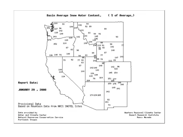
Check Beam Shear
Check Beam Shear. 245. 166. 245. Bending moment design. 2.5m. Short direction. Central band ratio =. Central band of short direction = 0.83 As = 0.83 (10.1)=8.6cm 2. Footing Design Part II Combined footing. Example 1. Design a combined footing As shown. Dimension calculation
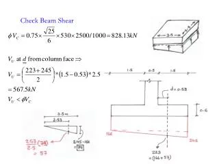

Check Beam Shear
E N D
Presentation Transcript
245 166 245 Bending moment design 2.5m Short direction
Central band ratio = Central band of short direction = 0.83 As = 0.83 (10.1)=8.6cm2
Footing Design Part II Combined footing
Example 1 Design a combined footing As shown
Dimension calculation The base dimension to get uniform distributed load 2000kN 800 kN 1200 kN A x1=0.2m x2=6.2m x 800(0.2)+1200(6.2)=2000(x) x = 3.8m 800 kN 1200 kN Try thickness =80cm 2x =7.6 m
Check for punching Shear d = 730 mm 1.13m 0.765 A
Draw S.F.D & B.M.D Stress under footing = 190 *1.8 = 342 kN/m
Check for beam shear b = 1800mm, d = 730mm
Bending moment Short direction Under Column A
Under Column B Shrinkage Reinforcement in short direction
Footing Design Part III Combined footing, strip footing, & Mat foundation
Example 2 Design a combined footing As shown
1950kN 1200 kN 750 kN A x2=4.2m x Dimension calculation The base dimension to get uniform distributed load 750(4.2)+1200(0.2)=1950 (x) x = 1.75m x1=0.2m
Check for punching Shear h= 750mm d = 732 mm A B2=1m B1=4m
Empirical S.F.D & B.M.D m Convert trapezoidal load to rectangle Mmax Clear distance between column B in moment design = ave. width = 2.5m
b Y=1.5m 1m x 4m Check for beam shear d = 665mm
Bending moment Long direction Top Bottom
Bending moment Short direction Under Column A
Under Column B Shrinkage Reinforcement in short direction
Example 3 (Strip footing) Design a combined footing As shown
Dimension calculation The base dimension to get uniform distributed load 3040kN 800 kN 1280 kN 960 kN A Assume L1=0.6 x1=5.2m L2 x2=10.7m x 800(0.6)+1280(5.1)+960(10.6)= 3040 (x) x = 5.65m, 2(x)=11.3m L2=11.3 -(10.6)=0.7
Check for punching Shear h = 700 mm d=630mm Example B You can check other columns
Draw S.F.D & B.M.D Stress under footing = 195 *1.8 = 351 kN/m
Check for beam shear b = 1800mm, d = 630mm
Bending moment Long direction Design Short direction as example 1 (lecture 11)
General Example, Ref. 2 Modified load