Download
1 / 20
240 likes | 779 Views
COMMUNICATION SYSTEM EECB353 Chapter 2 Part I AMPLITUDE MODULATION. Azlina Abdullah Dept of Electronics & Communication Engineering Universiti Tenaga Nasional http://metalab.uniten.edu.my/~shafinaz. Continuous-Wave (CW) Modulation. Contents: Amplitude Modulation (AM)

E N D
COMMUNICATION SYSTEM EECB353Chapter 2 Part I AMPLITUDE MODULATION Azlina Abdullah Dept of Electronics & Communication Engineering UniversitiTenagaNasional http://metalab.uniten.edu.my/~shafinaz
Continuous-Wave (CW) Modulation Contents: • Amplitude Modulation (AM) • Coefficient of Modulation & Percent of Modulation • AM Power Distribution • AM Modulator Circuit • AM Demodulator • Rectifier Detector • Envelope Detector • Superheterodyne Receiver • Double Sideband Suppressed Carrier (DSBSC) • Single Sideband (SSB) System • AM Single Sideband Full Carrier (SSBFC) • AM Single Sideband Suppressed Carrier (SSBSC) • AM Single Sideband Reduced Carrier (SSBRC) • AM Independent Sideband • AM Vestigal Sideband • Advantage of SSB Transmission • Disadvantage of SSB Transmission Reference: • Tomasi, Chapter 4,5,6
Introduction to CW • CW is the basis of analog communication system. There are two types of CW modulation namely: • Amplitude Modulation (AM) – amplitude of carrier varied according to message signal. • Angle Modulation– instantaneous frequency or phase of carrier varied according to message signal.
Introduction to CW • Information signals are transported between Tx and Rx over some form of transmission medium. • However, the original information signals are seldom in a form that is suitable for transmission. • They must be transformed from their original form into a form that is more suitable for transmission.
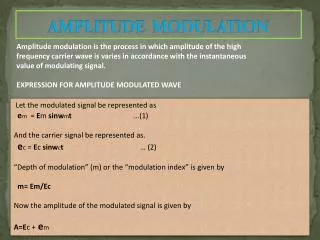
Introduction to CW • The process of impressing low frequency information signals onto a high frequency carrier signal is called modulation. • Demodulation is the reverse process where the received signal is transformed to their original form. • Amplitude Modulation (AM) is the process of changing the amplitude of a relatively high frequency carrier signal in proportion with the instantaneous value of the modulating signal. • High frequency carrier signal is also termed the radio-frequency (RF) signal because it is at a high-enough freq to be transmitted through free space as a radio wave. • Low frequency information signal is also term such as modulating signal, intelligence, audio signal.
Amplitude Modulation Envelope • Most commonly used is AM double-sideband full carrier(DSBFC), or sometimes called conventional AM or AM. • NB : • Repetition rate of the envelope ≈ frequency of the modulating signal. • Shape of the envelope ≈ shape of the modulating signal AM Envelope Generation
AM Envelope • Example – An AM signal can be produced by using instantaneous amplitude of the information signal (the baseband or modulating signal) to vary the peak amplitude of a higher-frequency signal. • Figure (a) shows a 1kHz sinewave, which combined with the 10kHz signal shown in Figure (b) to produce the AM signal in Figure (c). • If the peaks of the individual waveform of the modulating signal are joined, the resulting envelope resembles the original modulating signal. • It repeats at the modulating frequency and the shape of each “half” (i.e positive or negative) is the same as that of the modulating signal. (a) Modulating Signal (b) Carrier Signal (c) Modulated Signal
AM Frequency Spectrum and Bandwidth • Output envelope contains of dc voltage, carrier frequency, the sum (fc + fm) and difference (fc – fm) frequencies. • Bandwidth, B = difference between highest USB and lowest LSB i.e B = 2fm(max). • Figure below shows the frequency spectrum for an AM waveform Carrier Lower sideband (LSB) Upper sideband (USB) Amplitude Lower Side Frequencies (LSF) Upper Side Frequencies (USF) fc- fm(max) fc fc+ fm(max) Bandwidth, B
AM Frequency Spectrum- Sidebands (c) (a) (b) (d) freq The AM wave is the algebraic sum of the carrier and upper and lower sideband sine waves. (a) Intelligence or modulating signal. (b) Lower sideband. (c ) Carrier. (d ) Upper sideband. (e ) Composite AM wave.
Example 1 • For an AM DSBFC modulator with a carrier frequency, fc = 100 kHz and a maximum modulating signal frequency, fm(max) = 6 kHz, find • Frequency limit for upper and lower sideband. • Bandwidth. • Upper and lower side frequencies produced when the modulating signal is a single frequency 4 kHz tone. • Draw the output frequency spectrum. • A standard AM broadcast station is allowed to transmit modulating frequencies up to 5 kHz. If the AM station is transmitting on a frequency of 980 kHz, what are sideband frequencies and total bandwidth?
Coefficient & Percent of Modulation • Coefficient of Modulation,m (or modulation index or modulation factor or degree or depth of modulation), is a term used to describe the amount of amplitude change present in the AM waveform. • Mathematically, the modulation coefficient, where m = modulation coefficient (unitless) Em= peak change in the amplitude of output waveform voltage (volts) Ec = peak amplitude of the unmodulated carrier voltage (volts)
Derivation… • Percentage of Modulation can be derived as follows: then, and where Vmax = Ec + Em Vmin = Ec - Em
Derivation… • The peak change in the amplitude of the output wave, Em = sum of voltages from upper and lower side frequencies i.e Em = Eusf + Elsf and Eusf = Elsf , then where Eusf = peak amplitude of upper side frequencies Elsf = peak amplitude of lower side frequencies Note If M = 100%, when Em = Ec and Vmin = 0V.
Coefficient & Percent of Modulation or • Percent Modulation,M is m stated as a percentage i.e • When Em = Ec, i.e m = 1, there is no distortion at the output signal. • When Em = 0, i.e m = 0, we have the original, unmodulated carrier. • When m > 1, overmodulation is said to be present. • Generally, amplitude of message signal should be less than amplitude of carrier signal to avoid overmodulation.
Coefficient & Percent of Modulation (a) modulating signal (b) unmodulated signal (c) 50% modulated wave (m = 0.5) (d) 100% modulated wave (m = 1.0)
Overmodulation and Distortion The modulation index should be a number between 0 and 1. If the amplitude of the modulating voltage is higher than the carrier voltage, m will be greater than 1, causing distortion. If the distortion is great enough, the intelligence signal becomes unintelligible. Coefficient & Percent of Modulation
Overmodulation and Distortion Distortion of voice transmissions produces garbled, harsh, or unnatural sounds in the speaker. Distortion of video signals produces a scrambled and inaccurate picture on a TV screen. Coefficient & Percent of Modulation
Coefficient & Percent of Modulation Figure Distortion of the envelope caused by overmodulation where the modulating signal amplitude Vmis greater than the carrier signal Vc.
Example 2 • A) For the AM waveform shown, determine • Peak amplitude of the upper and lower side frequencies. • Peak amplitude of the unmodulated carrier. • Peak change in the amplitude of the envelope. • Coefficient of modulation. • Percent modulation. Vmax = 18Vp Vmin = 2Vp • B) The peak to peak value of an AM signal is 30V. The peak to peak value of the modulating signal is 12V. Calculate the percentage of modulation.
Vmin = 3Vp Vmax =10Vp • A 2MHz carrier signal is modulated with a 20 kHz modulating signal to produce an AM waveform as in Figure above. Determine: • Upper and lower side frequencies [2 marks] • Coefficient of modulation and percent modulation [2 marks] • Peak amplitude of the modulated carrier and the upper/lower side peak voltage [2 marks]