Understanding Amplitude Modulation in Communication Electronics
250 likes | 360 Views
Learn the basics of amplitude modulation, characteristics, modulation index measurement, power relationships, Quadrature AM, and Suppressed-Carrier AM in this informative guide.

Understanding Amplitude Modulation in Communication Electronics
E N D
Presentation Transcript
communication Electronics By M Z khan Amplitude Modulation
Amplitude Modulation is the simplest and earliest form of transmitters • AM applications include broadcasting in medium- and high-frequency applications, CB radio, and aircraft communications Introduction
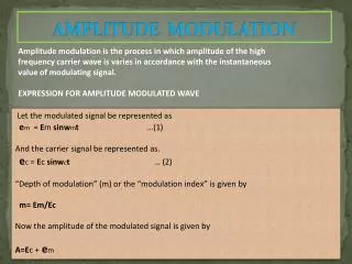
Basic Amplitude Modulation • The information signal varies the instantaneous amplitude of the carrier
AM Characteristics • AM is a nonlinear process • Sum and difference frequencies are created that carry the information
Modulation Index - The ratio between the amplitudes between the amplitudes of the modulating signal and carrier, expressed by the equation: Full-Carrier AM: Time Domain
When the modulation index is greater than 1, overmodulation is present Overmodulation
Two or more sine waves of different, uncorrelated frequencies modulating a single carrier is calculated by the equation: Modulation Index for Multiple Modulating Frequencies
Measurement of Modulation Index Insert fig. 3.7
Time domain information can be obtained using an oscilloscope • Frequency domain information can be calculated using Fourier methods, but trigonometric methods are simpler and valid • Sidebands are calculated using the formulas at the right Full-Carrier AM: Frequency Domain Insert formulas 3.11, 3.12.3.13
Signal bandwidth is an important characteristic of any modulation scheme • In general, a narrow bandwidth is desirable • Bandwidth is calculated by: Bandwidth
Power in a transmitter is important, but the most important power measurement is that of the portion that transmits the information • AM carriers remain unchanged with modulation and therefore are wasteful • Power in an AM transmitter is calculated according to the formula at the right Power Relationships
Two carriers generated at the same frequency but 90º out of phase with each other allow transmission of two separate signals • This approach is known as Quadrature AM (QUAM or QAM) • Recovery of the two signals is accomplished by synchronous detection by two balanced modulators Quadrature AM and AM Stereo
Full-carrier AM is simple but not efficient • Removing the carrier before power amplification allows full transmitter power to be applied to the sidebands • Removing the carrier from a fully modulated AM systems results in a double-sideband suppressed-carrier transmission Suppressed-Carrier AM
The two sidebands of an AM signal are mirror images of one another • As a result, one of the sidebands is redundant • Using single-sideband suppressed-carrier transmission results in reduced bandwidth and therefore twice as many signals may be transmitted in the same spectrum allotment • Typically, a 3dB improvement in signal-to-noise ratio is achieved as a result of SSBSC Single-Sideband AM
DSBSC and SSB Transmission Insert fig. 3.15