Download

1 / 42
430 likes | 637 Views
Topic 2: Heat Exchanger Fundamentals, Recuperative Heat Exchangers. Heat Exchangers : UA-LMTD Design Method e -NTU Design Method An Example. Heat Exchangers.

E N D
Topic 2: Heat Exchanger Fundamentals, Recuperative Heat Exchangers • Heat Exchangers: • UA-LMTD Design Method • e -NTU Design Method • An Example
Heat Exchangers A heat exchanger is a device for transferring heat from one fluid to another. There are three main categories: Recuperative, in which the two fluids are at all times separated by a solid wall; Regenerative, in which each fluid transfers heat to or from a matrix of material; Evaporative (direct contact), in which the enthalpy of vaporization of one of the fluids is used to provide a cooling effect.
Heat Exchanger (HX) Design Methods HX designers usually use two well-known methods for calculating the heat transfer rate between fluid streams—the UA-LMTD and the effectiveness-NTU (number of heat transfer units) methods. Both methods can be equally employed for designing HXs. However, the -NTU method is preferred for rating problems where at least one exit temperature is unknown. If all inlet and outlet temperatures are known, the UA-LMTD method does not require an iterative procedure and is the preferred method.
LMTD (Log Mean Temperature Difference) The most commonly used type of heat exchanger is the recuperative heat exchanger. In this type the two fluids can flow in counter-flow, in parallel-flow, or in a combination of these, and cross-flow. The true mean temperature difference is the Logarithmic mean Temperature difference (LMTD), is defined as
Heat Transfer Rate of a Heat Exchanger The heat transferred for any recuperative heat exchanger can be calculated as(refer to the diagram shown on the previous slide):
Heat Exchanger UA-LMTD Design Method Where U is the overall heat transfer coefficient (and is assumed to be constant over the whole surface area of the heat exchanger).
Effectiveness of a 6-row, 6-pass plate fin-and-tube cross counterflow HX
A HX Example: A schematic representation of a hybrid central receiver is shown in the following slide (Slide #12). In this system, molten nitrate salt is heated in a central receiver to temperature as high as 1,050oF (565oC). The molten salt is then passed through a heat exchanger, where it is used to preheat combustion air for a combined-cycle power plant. For more information about this cycle, refer to Bharathan et. Al. (1995) and Bohn et al. (1995). The heat exchanger used for this purpose is shown in Slide #13. The plates of the heat exchanger are made of steel and are 2 mm thick. The overall flow is counter-flow arrangement where the air and molten salt both flow duct-shape passages (unmixed). The shell side, where the air flow takes place, is baffled to provide cross flow between the lateral baffles. The baseline design conditions are:
A HX Example: (continued) Air flow rate: 0.503 kg/s per passage (250 lbm/s) Air inlet temperature: 340oC (~650oF) Air outlet temperature: 470oC (~880oF) Salt flow rate: 0.483 kg/s per passage (240 lbm/s) Salt inlet temperature: 565oC (~1050oF) Salt outlet temperature: 475oC (~890oF) Find the overall heat-transfer coefficient for this heat exchanger. Ignore the fouling resistances. Solution:
Recuperative Heat Exchangers: • Definition of Recuperative HX • Types of Recuperative HX • Design Factors • Examples A Recuperative Heat Exchanger (HX) is one in which the two fluids are separated at all times by a solid barrier.
Waste-Heat water-Tube Boiler Shell Boiler using Waste Gas
Gas-to-Gas Heat Recovery with a Plate-Fin Heat Exchanger A A
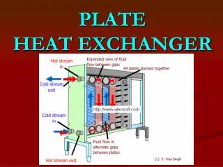
Liquid-to-Liquid Plate-Fin Heat Exchanger
Example 5.4 A flat surface as shown in the previous slide has a base temperature of 90oC when the air mean bulk temperature is 20oC. Air is blown across the surface and the mean heat transfer coefficient is 30 W/m2-K. The fins are made of an aluminum alloy; the fin thickness is 1.6 mm, the fin height is 19 mm, and the fin pitch is 13.5 mm. Calculate the heat loss per m2 of primary surface with and without the fins assuming that the same mean heat transfer coefficient applies in each case. Neglect the heat loss from the fin tips and take a fin efficiency of 71%.
-NTU Method (Effectiveness — Number of Thermal Units Method)
-NTU (Effectiveness against NTU) for shell-and-tube heat exchangers (with 2 shell passes and 4, 8, 12 tube passes)
Characteristics of -NTU Chart • For given mass flow rates and specific heats of two fluids the value of depends on the NTU and hence on the product (UAo). Thus for a given value of U the NTU is proportional to Ao. It can then be seen from the -NTU chart that increasing Ao increases and hence the saving in fuel. • The capital cost of the heat exchanger increases as the area increases and -NTU chart shows that at high values of large increase in area produce only a small increase in . • The NTU and hence the effectiveness, can be increased for a fixed value of area by increasing the value of the overall heat transfer coefficient, U.
Increasing HX with Fixed Ao (1) The NTU, and hence can be increased for a fixed value of the area by increasing the value of the overall heat transfer coefficient, U, which can be increased by increasing the heat transfer coefficient for one or both of the individual fluids. The heat transfer coefficient can be increased by reducing the tube diameter, and/or increasing the mass flow rate per tube.
Increasing HX with Fixed Ao (2) • Since , for a constant total mass flow rate the number of tubes per pass must be reduced correspondingly if the mass flow rate per tube is increased. • Also, the heat transfer area is given by , where n is the number of tubes per pass, and p is the number of tube passes. Therefore, to maintain the same total heat transfer area for a reduced tube diameter in a given type of heat exchanger, it is necessary to increase the length of the tubes per pass, L, and/or the number of tubes per pass (which will reduce the heat transfer rate.) • The design process is therefore an iterative process in order to arrive at the optimum arrangement of tube diameter, tube length, and number of tubes.
Overall HX Design Considerations • Altering the inside diameter of a tube to increase the heat transfer coefficient for flow through the tube will alter the heat transfer on the shell side. • A full economic analysis also requires consideration of the pumping power for both fluids. Pressure losses in fluid flow due to friction, turbulence, and fittings such as valves, bends etc. are proportional to the square of the flow velocity. The higher the fluid velocity and the more turbulent the flow the higher is the heat transfer coefficient but the greater the pumping power.
Example 5.5 (a) A shell-and-tube heat exchanger is used to recover energy from engine oil and consists of two shell passes for water and four tube passes for the engine oil as shown diagrammatically in the following figure. The effectiveness can be calculated based on Eastop Equation (3.33). For a flow of oil of 2.3 kg/s entering at a temperature of 150oC, and a flow of water of 2.4 kg/s entering at 40oC, use the data given to calculate: (i) the total number of tubes required; (ii) the length of the tubes; (iii) the exit temperatures of the water and oil; (iv) the fuel cost saving per year if water heating is currently provided by a gas boiler of efficiency 0.8. (b) What would be the effectiveness and fuel saving per year with eight tube passes?
”Use EES for Eastop Example 5.5" {hot oil} m_dot_H=2.3 {oil mass flow rate, kg/s} t_H1=150 {hot oil inlet temperature, C} cp_H=2.19 {mean spefici heat of oil, kJ/kg-K} rho_H=840 {mean oil density, kg/m^3} C_H=m_dot_H*cp_H {hot fluid capacity, kW/K} {cold water} m_dot_C=2.4 {water mass flow rate, kg/s} t_C2=40 {cold water inlet temperature, C} cp_C=4.19 {mean specific heat of water, kJ/kg-K} C_C=m_dot_C*cp_C {cold fluid capacity, kW/K} {data} eta_boiler=0.8 {gas boiler efficiency} v_H=0.8 {oil velocity in the tube, m/s} eta_Hx=0.7 {require HX effectiveness} n_pass=4 {four pass heat exchanger} d_i=0.005 {tube inside diameter, m} d_o=0.007 {tube outside diameter, m} U=0.400 {overall heat transfer coefficient, kW/m^2-K} t_hours=4000 {annual usage, h} cost=1.2 {cost of water heating, p/kWh}
{a(i): calculate the total number of tubes required} • V_dot_H=m_dot_H/rho_H • A_cross=V_dot_h/v_H • A_1=PI*d_i^2/4 • n_tube=A_cross/A_1*n_pass • n_tube=697 [tubes] • {a(ii): calculate the length of the tubes} • R=min(C_H,C_C)/max(C_H,C_C) • eta_HX=(1-exp(-NTU*(1-R)))/(1-R*exp(-NTU*(1-R))) • NTU=U*A_o/min(C_H,C_C) • A_o=PI*d_o*n_tube*L_tube • L_tube=1.27 [m] • {a(iii): calculate the exit temperature of oil and water} • Eta_HX=C_H*(t_H1-t_H2)/(min(C_h,C_C)*(t_H1-t_C2)) • C_H*(t_H1-t_H2)=C_C*(t_C1-t_C2) • t_C1=78.6 [C]; t_H2=73.0 [C]
{a(iv): calculate the total heat transfer and fuel cost saving per year} • Q_dot=C_C*(t_C1-t_C2) • Fuel_saving=Q_dot*t_hours*cost/(eta_boiler*100) • Fuel_saving=23271 [British Pounds] • {b(v): calculate eta2_hx if double Ao} • NTU2=2*NTU • eta2_HX=(1-exp(-NTU2*(1-R)))/(1-R*exp(-NTU2*(1-R))) • eta2_HX=0.881 • {b(vi): calulate t_H2, t_C2 and fuel_saving} • eta2_HX=C_H*(t_H1-t2_H2)/(min(C_h,C_C)*(t_H1-t_C2)) • C_H*(t_H1-t2_H2)=C_C*(t2_C1-t_C2) • Q2_dot=C_C*(t2_C1-t_C2) • Fuel2_saving=Q2_dot*t_hours*cost/(eta_boiler*100) • Fuel2_saving=29279 [British Pounds]