
IRMIS
E N D
Presentation Transcript
IRMIS RDBCore – integrated s/w, h/w and cable databases D. Dohan, Mar 9, 2005
PV ERD – essential elements An EPICS record has a name and is of a specific type. Each record type has a DBD record definition loaded in Records are loaded into (belong to) an IOC. (Channel Access does not need to know which IOC the record belongs to, but the developer does) is part of Records have fields, which are name/value pairs. A record instance is defined by its set of field/value pairs. These instance values are contained in .db files. A record definition may span several .db files No record-type specific tables – the crawler ‘discovers’ the implemented record types. Schema and crawler site neutral
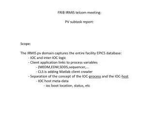
PV schema • more of a software system schema – capturing the entire system logic • ioc configuration and boot information • database definitions • inter IOC links • CA clients (adl now, alh coming, others..) • time stamp – like CVS tag • exhaustive PV list is required crawler • mining PV info to extract control system hardware components ~70% of initial APS components ‘discovered’ by PV data mining • possible use in name server?
IRMIS Components • What is a component? • “ a constituent element, as of a system”… (Google) • unit replaceable physical entity associated with the accelerator • IO card, chassis, serial link, .. • more primitive granularity than a ‘device’ • do not assign a high level physics ‘role’ to a component • less subjective – no naming convention issue • more on this later • more geared to how the facility is assembled, rather than how it functions. • component approach was originally based on EPICS device-types • now extended to cover all accelerator equipment • mechanical components, physical spaces, ac distribution • multi-hierarchy
Component RDB –essential elements The basic entity in the component database is the concept of a component type. Any component instance is of a specific type. Each component is assigned a logical # (the EPICS io addr) and a physical descriptor to distinguish similar hierarchy siblings At this point, we can begin tabulating all of the components in the accelerator - the table contains component_id/component_type pairs. is a In IRMIS, each control component is controlled by, or passes datato a unique control parent. This 1:M relation defines a control hierarchy is controlled by ispowered by The database table now contains the cmpnt_id, the cmpnt_type and its control_parent_id, which points to another component instance somewhere in the database. is housed by ---------- Issue: The database contains only the components that an IOC can ‘see’. Another issue was how to handle the ‘location’ attribute – limited queryability. An additional hierarchy is defined – the housing hierarchy. Each component is ‘housed’ within another component within the DB. Every device has a housing parent. The location attribute is replaced by the housing hierarchy. May now add non control components An additional hierarchy has been added – the power hierarchy. Any component gets its power feed from a unique power source, which is component in the DB. Component table:
Multiple Hierarchies • attempt to capture orthogonal hierarchical concepts • who controls the component? • where is it located? • where does the component derive its power? • more than just another attribute – allows (hierarchy based) querying • what other components are controlled by this c-parent? • what is located in this chassis? what else is nearby? • what other components are powered by the same circuit? • concept of ‘path’ provided by the hierarchical topology • components need not be members of all 3 hierarchies • every component is a member of the housing hierarchy • it must be located somewhere, even if it is in a stores cabinet • every component is stored only once in the database
Assembling a (sub) facility id type cpid hpid ppid 1 room - 0 - 1 2 rack - 1 - 5 3 rack - 1 - 4 3 2 4 ac panel - 1 0 5 circuit - 4 4 6 - 6 pwr strip 2 5 7 chassis 9 2 8 13 7 8 chas. ps - 7 6 9 10 15 9 cpu 0 7 7 14 10 1014 7 7 7 8 11 gpib link 10 10 - 11 12 gpib dev 11 2 6 12 13 chassis - 3 - 14 1014 - 13 - 15 1014D - 13 -
Connections vs components • in the case of the 1014 – only the serial number is changed when swapping spares.. • the id of the row in the db is not changed – the connection, or system configuration, has not changed • the software (i.e. the PV) is only aware of the connection, not of the serial number of the module. • if the 1014 is replaced with a pin compatible module (eg the 1014D above), then both the serial # and the component type changes. The connection id remains the same. The PV does not know the difference. • The user is never directly aware of the component/connection id. • each line in the component table (‘relation’ in RDB speak) represents a multi-dimensional abstract connection. The components making up the connection are merely attributes of the connection
Cable ERD Each component has a set of ports - (0 or more) A cable is something with a connector. Has a color and label. The cable is what the user handles, ie connects between ports To handle the wide variety of cable types, each pin in each port is stored in the database. The pins accept the individual ‘signals’ carried in the conductors in a multi-strand connector. is a ispowered by is controlled by The user connects cables, the database connects pins. is housed by Pins have signals, which will eventually relate to software PVs. is part of With the component database infrastructure in place, the cable database is surprisingly simple. Most of the complexity is handled in the hierarchical component database. is part of is part of The cable and component schema is site neutral. There is no APS or SNS signature: there is not even any evidence that we are modelling an accelerator.
Cables and components – (discussion, future) • a cable transmits a signal from an output of one component to an input of another component. • the cable does not have a signal name – each port does • the cable has 2 signal names associated with it • the component takes its inputs and transforms them into a set of outputs • concept of a component as a signal transformer • eg : light box O = I • eg: fan-out Oj = I (j=1,8) • allow end-to-end signal tracing (for simple xfmr’s) • abstract the notion of component as a signal XFMR, and store in the RDB - this is still not functional decomposition/description. • expanded characterization of signal types – to simplify cable entry
wiring list/interface control document equipment Wiring list
Wiring list wiring list/interface control document equipment
Extending component types • Extend component types to include accelerator equipment • put the external component into the component RDB • wiring list information is now handled by the cable database • gives the control engineer a better feel for how the system as a whole is supposed to work • can be extended to include power supplies • high current power feeds are generalized signals • power supply ‘transforms’ the drive signal to high current • storage of this abstract transformation within the RDB • more abstract: can be extended to include magnets • I/P signal is high current, output signal is B-field (abstract) • more abstract – extension to the beam as a component • I/P signal = B, output signal = X,Y,etc BPM signal. Perhaps not, but this is what the modelers in essence do. • can also be extended (downward) to replaceable board level components – fpga, etc
Components vs devices (and naming conventions) Suppose that all the component transforms are stored in the database – would this be a basis around which to model physics data, at the same time providing the engineer with the component/assembly description? Beam PS controller Power Supply Magnet This schema is still site-neutral – only the system assembly data (the configuration instance data) is site specific. Functional modeling replaced by component transfer functions. Now that all the components are in the database, what about another hierarchy - the physics device hierarchy?
revive PV mining script to deduce installed H/W – establishes sw/hw link dbior reports EPICS device supportin RDB. Table for supported device_types and their associated device support RDBCore - Work in Progress is a loaded in is controlled by ispowered by is housed by is part of is part of is part of is part of
IRMIS Future (cont’d) • IRMIS as a core (site-neutral) RDB schema and basic applications – only 28 tables are in RDBCore at present. • RDB Extensions: • How can local site specific extensions be built to be (at least partially) reusable? (e.g. framework approach) • Example – ioc applications based on the component DB • Universal component type table – at least for the EPICS supported devices. Locally extensible